I have three bad ones and I would be more than willing to send them to you if you could promise to fix one for me!
If you are interested please email me @ rock106_5@hotmail.com
Thanks Nick
Just have done, sorry it's taken me this long, I just moved house, and got a pair of mint Acoustic AR-2ax to distract me
")
Hello SatinMill , I also have 2 HF2001s that are down and out and would love to get them repaired or indeed do it myself . The SEAS 0737s which have replaced them in my 332s are OK but I feel they are missing something .
If you have a thread on this repair or could let us know your sequence and any issues I'm sure there's a few here would appreciate it .
Thank you.
Just replied in PM too with what I did and a pic.
Question about inductors
Hi there,
After growing up listening to my Dad's Ditton 15XR's and running Ditton 33's since the start of my Hi-Fi ownership, I have recently aquired the speakers i've wanted for several years now - a pair of early Celestion 66's. Black baffles, MD500 mids, T1600 woofers and HF2000 tweeters. There is no date stamped inside the cabinets and no serial numbers either (space on the plate by the terminals left blank). The crossovers look totally original, with C4 and C5 being a total of 30uF and banks of ERIE A304 METALISED 2uf caps in the tweeter filters.
A re-cap of the crossovers has been intended from the start, and after studying this excellent thread I have bought Axon 36uf pairs for the bass filter, Sonicap Gen I 24uf (C5) and 4uf (c3) for the mid filter, and Sonicap Gen I 4uf and 6uf for the tweeter filters. ESR compensating resistors are all Mills MRA5 of the relevant values.
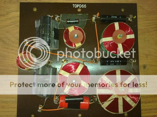
I am a little concerned by the current layout of the inductors. L3 and L4 are connected electrically reversed in one of the speakers (see pictures). My electrical knowledge is limited, however i read a post by alan-1-b earlier in the thread that the inductors should not be connected in reverse.. Would this have a significant audible effect?? There is no evidence of these crossovers ever being modified so they must have been wired this way during manufacture.
Also, the woofer on one speaker was wired out of phase, again no obvious evidence of tampering but I find it hard to believe they could have left the factory like this! Other audible traits are a dominant midrange and slightly rolled off treble, which seems to be in keeping with other owners' oberservations prior to a crossover re-cap. No nasty noises from either MD500s or HF2000s so hoping all is good with the drivers!
I would like to reverse L3 and L4 on one of the boards to keep them as electrically identical as possible, can anyone confirm this is the best way forward, or will it make no audible difference?? The woofer connections will be also be corrected.
Thanks in advance.
David.
Hi there,
After growing up listening to my Dad's Ditton 15XR's and running Ditton 33's since the start of my Hi-Fi ownership, I have recently aquired the speakers i've wanted for several years now - a pair of early Celestion 66's. Black baffles, MD500 mids, T1600 woofers and HF2000 tweeters. There is no date stamped inside the cabinets and no serial numbers either (space on the plate by the terminals left blank). The crossovers look totally original, with C4 and C5 being a total of 30uF and banks of ERIE A304 METALISED 2uf caps in the tweeter filters.
A re-cap of the crossovers has been intended from the start, and after studying this excellent thread I have bought Axon 36uf pairs for the bass filter, Sonicap Gen I 24uf (C5) and 4uf (c3) for the mid filter, and Sonicap Gen I 4uf and 6uf for the tweeter filters. ESR compensating resistors are all Mills MRA5 of the relevant values.
I am a little concerned by the current layout of the inductors. L3 and L4 are connected electrically reversed in one of the speakers (see pictures). My electrical knowledge is limited, however i read a post by alan-1-b earlier in the thread that the inductors should not be connected in reverse.. Would this have a significant audible effect?? There is no evidence of these crossovers ever being modified so they must have been wired this way during manufacture.
Also, the woofer on one speaker was wired out of phase, again no obvious evidence of tampering but I find it hard to believe they could have left the factory like this! Other audible traits are a dominant midrange and slightly rolled off treble, which seems to be in keeping with other owners' oberservations prior to a crossover re-cap. No nasty noises from either MD500s or HF2000s so hoping all is good with the drivers!
I would like to reverse L3 and L4 on one of the boards to keep them as electrically identical as possible, can anyone confirm this is the best way forward, or will it make no audible difference?? The woofer connections will be also be corrected.
Thanks in advance.
David.
Hello al, Ya just wanted to drop in on this great post, you guys hae done some great work here. This thing has been going for a long time. I hope all ditton lovers the best of luck and listening.
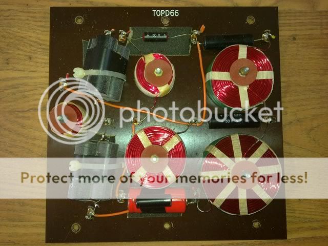
I also just got a set of the cool Ditton 66's and they are a 1977 make. Black and red elcap caps and parellel green ones. The circuit bord lay out looks just like David's. I think mine is the same wire conf. as yours Dave.
I got them for a fair price but have found that the tweeters are not working. That sucks, well not the only one. I will switch them with the HO737 19TFF1 tweeter and set up the cross over as follows. Replace caps with Solen 250v PA series as outlined…
C1, C2 = 6.2uF
C3, C4 = 3.9uF
C5 = 3.9uF
C6 = 2*36uF for 72uF
C7 = 24uF
C8 = 2*36uF for 72uF
May consider a 68uF @ C6 and 75uF @ C8 ??
ESR Resistors, Mills MRA-5 as outlined…
C1, C2 – 6.2uF = 0.5R
C5 – 3.9uF = 3.3R
C6 – 72uF = 1.5R
C7 – 24uF = 1.5R
C8 – 72uF = 1.0R
I was wondering if the cap and resister value has been fine tuned for this tweeter set to anyones liking?
For low price, Coles CE 4001 tweeters will work OK, -{with resistors fitted}.
CE 4001 is very similar to HF2000.
I think that Coles may have made HF2000 for Celestion years ago.
Has anyone tried or used this coles tweeter config.?
Again love this thread, took me two days to read through it but you guys really love your speakers!!!
Thanks...
Greg
read again !
Very briefly today only:-
For the SEAS tweeter do NOT use the 6.2uF capacitor, etc ...
I recommend you read through the thread again from where-ever I first mentioned it,
and continue till you find the recommended capacitor and resistor values for it,
at least for the necessary Parallel connected resistor,
if you do not want any tweeter attenuation with an L-pad of 2 resistors.
Find also where I posted about better sounding options for capacitors for mids and treble than the Solens for little extra money - it is worth it !
I am very busy, and cannot continue here now,
but I hope to be back here in about 2 weeks ...
and will continue about the SEAS tweeter then if you like ...
... and also about David878's inductors' question ...
... and whatever else I have not finished prior in the thread.
Hello again everyone,
I haven't posted here for years but I've finally done what I promised to do ages ago and opened up one of my 66s to have a look at the xover. The story so far is that my 66s are from the very last series, with the wooden fronts and the PCB crossovers. After buying them, and before this thread started, I took them to Wilmslow Audio and asked them to recap them and also replace the flimsy internal wiring and the binding posts. I've been using them happily ever since but also following this thread with enormous interest and chipping in once or twice.
On opening up one of the speakers my first discovery was that I made a mistake in post 162 (page 17) when posting links to the circuit diagrams for the different types of crossover. One type of crossover is called the "tagged board" crossover and I thought this was the PCB crossover because the speaker wires are attached to the board with tags or tabs. (Wimslow Audio removed my tags and hard-wired the speaker wires to the PCB to improve signal flow.) But it turns out I had them the wrong way round and in fact the tagged board is the older type and the type I have, the PCB, is the one that's NOT called the tagged board crossover unit.
Anyway here's a picture of mine as refurbished by Wilmslow Audio (you can click on the picture to enlarge it):
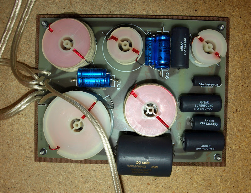
It seems to me that Wilmslow have done a very good job here. I'm almost sorry in a way because I was hoping I would find I could make the speakers sound even better than they already do! Starting with the blue caps on the left of the board (C8), the values are as follows, going clockwise round the board:
C8: One Alcap 60MFD 100V plus one Alcap 12MFD 100V.
C6: same as C8.
C5 (the black one immediately to the right of C6): Ansar CPA 4u J 450
C4: Ansar CPA 0u68 J 450
C3: Ansar Supersound CPA 3u3 J 400
C2: Ansar CPA 1u5 J 450
C1 (bottom right-hand corner): Ansar CPA 4u7 J 450
C7 (the great big one at the bottom): Wilmslow Supersound MKP 25.00uF +/- 5% 630V DC
If you then compare those values with those on the official Celestion circuit board diagram here:
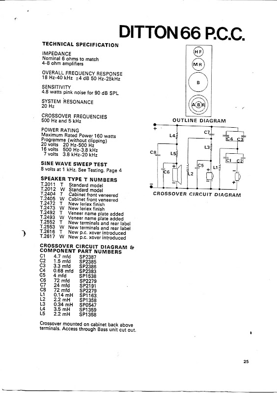
you find that Wilmslow have taken the trouble to substitute caps of identical values with the single exception of the big one at the bottom which is 25uF instead of 24uF - so close it surely makes no difference.
I can see some things that maybe wouldn't meet with Alan's complete approval - notably, caps of different values being mixed in parallel. But it seems to me likely that any improvements I could make would be more notional than audible. Does anyone have any thoughts?
By the way, if you want to compare this PCB with an unmodified one, Grahame posted a picture of the unmodded version in post 47, page 5.
I haven't posted here for years but I've finally done what I promised to do ages ago and opened up one of my 66s to have a look at the xover. The story so far is that my 66s are from the very last series, with the wooden fronts and the PCB crossovers. After buying them, and before this thread started, I took them to Wilmslow Audio and asked them to recap them and also replace the flimsy internal wiring and the binding posts. I've been using them happily ever since but also following this thread with enormous interest and chipping in once or twice.
On opening up one of the speakers my first discovery was that I made a mistake in post 162 (page 17) when posting links to the circuit diagrams for the different types of crossover. One type of crossover is called the "tagged board" crossover and I thought this was the PCB crossover because the speaker wires are attached to the board with tags or tabs. (Wimslow Audio removed my tags and hard-wired the speaker wires to the PCB to improve signal flow.) But it turns out I had them the wrong way round and in fact the tagged board is the older type and the type I have, the PCB, is the one that's NOT called the tagged board crossover unit.
Anyway here's a picture of mine as refurbished by Wilmslow Audio (you can click on the picture to enlarge it):
It seems to me that Wilmslow have done a very good job here. I'm almost sorry in a way because I was hoping I would find I could make the speakers sound even better than they already do! Starting with the blue caps on the left of the board (C8), the values are as follows, going clockwise round the board:
C8: One Alcap 60MFD 100V plus one Alcap 12MFD 100V.
C6: same as C8.
C5 (the black one immediately to the right of C6): Ansar CPA 4u J 450
C4: Ansar CPA 0u68 J 450
C3: Ansar Supersound CPA 3u3 J 400
C2: Ansar CPA 1u5 J 450
C1 (bottom right-hand corner): Ansar CPA 4u7 J 450
C7 (the great big one at the bottom): Wilmslow Supersound MKP 25.00uF +/- 5% 630V DC
If you then compare those values with those on the official Celestion circuit board diagram here:
you find that Wilmslow have taken the trouble to substitute caps of identical values with the single exception of the big one at the bottom which is 25uF instead of 24uF - so close it surely makes no difference.
I can see some things that maybe wouldn't meet with Alan's complete approval - notably, caps of different values being mixed in parallel. But it seems to me likely that any improvements I could make would be more notional than audible. Does anyone have any thoughts?
By the way, if you want to compare this PCB with an unmodified one, Grahame posted a picture of the unmodded version in post 47, page 5.
rwtomkins would you mind taking a pic of the speaker wire connection to the PCB ? I have Ditton 33s which on have just replaced the caps but didn't do the internal wiring as it looked like there wasn't enough room to solder the wires on without wrecking the connections. So i'd be interested to see how Wilmslow did it .
Thanks
Thanks
rwtomkins would you mind taking a pic of the speaker wire connection to the PCB ?
I'm very sorry but I can't at present. The speakers are in daily use and I only took a quick peek with the crossover still in situ. If or when I take the crossover right out, I'll be happy to photograph the other side but I'm not planning to just at the moment.
understand - if you can recall did they just drill through the board and solder the wire directly to the tracks ?
Yes, they suggested a soldered joint would be better than the push-on connectors and you can see from the picture that they've drilled through the board so I think you can be certain that if you saw the other side, you would simply find the bare cable ends soldered direct to the tracks.
Mind you, the other ends of the cables are still attached to the drivers with push-on connectors so you begin to wonder what was the point!
I'm hoping Alan will be back soon to comment. Meanwhile, David878, I think if I were in your place I'd be wary of changing the polarity of anything in the crossovers before hearing from Alan - I think this came up earlier in the thread and if I recall correctly there are reasons why the polarities of the inductors and even the drive units are sometimes reversed, though I don't know what those reasons are.
Thanks rw.
I may get round to replacing the internal wiring and solder the ends on to the tracks as when I replaced the caps I couldn't get the new wires into the board connectors- way too big.
By the way I replaced the blown HF2001s with the SEAS HO737 19TFF1 without changing the crossover atall .They sound OK to me but I didn't have the HFs working so its impossible to compare .
I would like to repair the HFs at some time but too busy at the moment.
Phil
Hello everyone
I hope its ok to jump into this massively long, but very informative thread. It took me a fortnight to read through it all but I'm so glad I did. I know I'll have to re-read at some stage as I'm just a novice really and a lot of it went over my head, but it has re-kindled my interest in DIY and I'd like to say thanks for that especialy to Mr Alan-1-b, as without his continued contributions and patients I think it may not have lasted as long as it has.
Anyway, here's my reason for posting
Having seen the circuit diagrams of the ditton 33 and the 44 on Page 25, post #246 & #247 of this thread I was surprised to find they were so different. I thought the 33 & 44 had the same tweeter & midrange drivers and thus would have the same filter circuits, except of course for the different bass drivers.
I have some Ditton 33's which had the tweeters replaced with Morel's of type Cat298. I have never felt totaly happy with these even after fitting 1.7 ohms in series and 10 ohms in parallel with the output from the treble crossover to reduce its output a bit.
Having read this thread and being re-motivated I want to change the tweeters for the Seas HO737 and also update/upgrade the Caps on the crossover board. I think my bass output is disproportionately louder than the other drivers so I'm hoping new caps will improve this situation.
Initialy I just want to replace the existing caps with similar but new electrolytics. This (hopefuly with your guidence and advice) is so I can adjust any treble filter components 'cheaply' if necessary to accomadate the HO737. Then at a later date upgrade to polyprops once it is successfully integrated into the system.
As I live in the UK, What would you recomend as a suitable replacement for the original caps? - which are all black with red tips and mounted on a PCB.
When I fit the seas tweeters will I need to alter any values of caps or add any resistance in the filter circuit, or would they be a suitable match by themselves?
Any advice greatfully appreciated.
Regards
Roy
Did all you Celetion fans see that a guy in England sold a pair of NOS in-box, Celestion Ditton 66 on E-Bay for GBP 1,170? (US $1865)? Plus GBP 250.00 shipping, which looks like it was intended to cover freight to USA. Not sure if the buyer was US or other. I've never seen a set go this high!
Did all you Celetion fans see that a guy in England sold a pair of NOS in-box, Celestion Ditton 66 on E-Bay for GBP 1,170? (US $1865)? Plus GBP 250.00 shipping, which looks like it was intended to cover freight to USA. Not sure if the buyer was US or other. I've never seen a set go this high!
What amazed me was that a) these were obviously not NOS at all but simply in good condition for their age, b) that the guy's last sale got negative feedback and c) that these weren't even late model 66s but the very earliest ones with the black fronts.
Mind you, a few days earlier, a pair of blackies that looked as though they'd been excavated from a tip went for £510. It makes you wonder what a good pair would go for.
Anyway, in response to Royville's post, hello and welcome to the enormous thread. I hope you get some good advice - unfortunately it won't come from me because I'm one of those who's usually asking the questions rather than providing the answers!
Components in Ditton 33
Hello everyone.
I apologise that I will again have to be brief, and thus only can deal in part today with 2 issues.
.
and "royville" posted:
"Having seen the circuit diagrams of the ditton 33 and the 44 on Page 25, post #246 & #247 of this thread I was surprised to find they were so different. I thought the 33 & 44 had the same tweeter & midrange drivers and thus would have the same filter circuits, except of course for the different bass drivers.
I have some Ditton 33's which had the tweeters replaced with Morel's of type Cat298. I have never felt totaly happy with these even after fitting 1.7 ohms in series and 10 ohms in parallel with the output from the treble crossover to reduce its output a bit."
Hi goalhanger and royville,
I suspect at least one, and perhaps more, of the components' values shown in the hand-drawn schematic for the Ditton 33 shown in #246 on Page 25 is a mistake.
In the midrange bandpass filter, the Series connected inductor which forms half the high-cut filter is highly unlikely to be 2mH.
I think the 2mH is likely to be the other inductor in that section ... in the Parallel arm of the low-cut filter, and the Series inductor is more likely to be 0.6mH as it is in the circuit for the Ditton 44 which may have the same mid-cone driver.
Also, the tweeter filter - I can believe the 12uF and 0.14mH, but 8uF for the input cap seems too large ... but it could be correct, depending on the Impedance of the HD1000 tweeter - which I do not know.
What did you two find actually printed on each of the capacitors in your 33s ?
- and is there anything printed on your inductors ?
One of you does not have working HD1000s but if any reader here does, please measure the DC resistance of as many samples as you can and Post here so that we can assess what needs to be taken into account when modifying the crossover to close to optimum for other tweeters with different Impedances.
That Morel tweeter is not bad, though it has higher Sensitivity than the old HD1000 thus will need an L-pad to match it to the circuit,
and to calculate optimally for that we do need to know the Impedance of the HD1000 if the 0.14mH inductor is to be kept in that section.
1.7 and 10 ohm resistors may not be the optimum for the L-pad for impedance match to the circuit.
Similar is the case if modifying to accomodate the SEAS tweeter there.
Is that midrange cone the same diameter as the one in the Ditton 44 ?
I have only a very small photo of a 33 here - the cone looks same diameter as in the 44, but it could be 1" less.
There was apparently 2 different versions of the mid-cone used in the 44 - one for each of the 2 vintages of models.
More on this later, but for now please Post whatever you can about the above.
.
*** *** *** *** ***
.
And to the gentlemen enthusiasts who posted above on this page !
:
The Ditton 66 is a very good loudspeaker, but ebay selling prices have reached the ridiculous because those old drivers, particually the mid-domes, are unlikely to be in good enough condition in most cases to be worth that.
For less than that recent sale's amount of money a similar sized loudspeaker could be designed and built with modern drivers to give similar sound to a 66, and better than the apparently not-as-good 662 {and 442, etc ...}.
I think there is a bit of a Fashion-Craze for 66s currently, and I hope what I have been contributing in this thread about re-conditioning them has not been part of what has caused people to bid so high.
I do understand the wanting of a speaker with that type of sound, and obviously few if any current manufacturers have models to satisfy those enthusiasts, but one should be reasonable and consider the service-life of what one is paying for.
.
*** *** *** ***
.
I'll get back here when I can, and hopefully continue with other things in this thread then.
Hello everyone.
I apologise that I will again have to be brief, and thus only can deal in part today with 2 issues.
.
I have Ditton 33s which on have just replaced the caps
and "royville" posted:
"Having seen the circuit diagrams of the ditton 33 and the 44 on Page 25, post #246 & #247 of this thread I was surprised to find they were so different. I thought the 33 & 44 had the same tweeter & midrange drivers and thus would have the same filter circuits, except of course for the different bass drivers.
I have some Ditton 33's which had the tweeters replaced with Morel's of type Cat298. I have never felt totaly happy with these even after fitting 1.7 ohms in series and 10 ohms in parallel with the output from the treble crossover to reduce its output a bit."
Hi goalhanger and royville,
I suspect at least one, and perhaps more, of the components' values shown in the hand-drawn schematic for the Ditton 33 shown in #246 on Page 25 is a mistake.
In the midrange bandpass filter, the Series connected inductor which forms half the high-cut filter is highly unlikely to be 2mH.
I think the 2mH is likely to be the other inductor in that section ... in the Parallel arm of the low-cut filter, and the Series inductor is more likely to be 0.6mH as it is in the circuit for the Ditton 44 which may have the same mid-cone driver.
Also, the tweeter filter - I can believe the 12uF and 0.14mH, but 8uF for the input cap seems too large ... but it could be correct, depending on the Impedance of the HD1000 tweeter - which I do not know.
What did you two find actually printed on each of the capacitors in your 33s ?
- and is there anything printed on your inductors ?
One of you does not have working HD1000s but if any reader here does, please measure the DC resistance of as many samples as you can and Post here so that we can assess what needs to be taken into account when modifying the crossover to close to optimum for other tweeters with different Impedances.
That Morel tweeter is not bad, though it has higher Sensitivity than the old HD1000 thus will need an L-pad to match it to the circuit,
and to calculate optimally for that we do need to know the Impedance of the HD1000 if the 0.14mH inductor is to be kept in that section.
1.7 and 10 ohm resistors may not be the optimum for the L-pad for impedance match to the circuit.
Similar is the case if modifying to accomodate the SEAS tweeter there.
Is that midrange cone the same diameter as the one in the Ditton 44 ?
I have only a very small photo of a 33 here - the cone looks same diameter as in the 44, but it could be 1" less.
There was apparently 2 different versions of the mid-cone used in the 44 - one for each of the 2 vintages of models.
More on this later, but for now please Post whatever you can about the above.
.
*** *** *** *** ***
.
And to the gentlemen enthusiasts who posted above on this page !
:
The Ditton 66 is a very good loudspeaker, but ebay selling prices have reached the ridiculous because those old drivers, particually the mid-domes, are unlikely to be in good enough condition in most cases to be worth that.
For less than that recent sale's amount of money a similar sized loudspeaker could be designed and built with modern drivers to give similar sound to a 66, and better than the apparently not-as-good 662 {and 442, etc ...}.
I think there is a bit of a Fashion-Craze for 66s currently, and I hope what I have been contributing in this thread about re-conditioning them has not been part of what has caused people to bid so high.
I do understand the wanting of a speaker with that type of sound, and obviously few if any current manufacturers have models to satisfy those enthusiasts, but one should be reasonable and consider the service-life of what one is paying for.
.
*** *** *** ***
.
I'll get back here when I can, and hopefully continue with other things in this thread then.
Last edited:
xover appears correct
Hi Alan,
I’ve thoroughly checked the 33 crossover circuit against my crossover units and it looks totally correct to me. I can’t confirm the value of the 2mH inductor but it is physically the largest one on the crossover and it is drawn in the correct position on the circuit of ‘#246 on Page 25’. Is there a way to measure these unknown inductors? (I only have a scope, Fluke 87 and PC at my disposel).
Also the 8uF cap in the treble circuit is correct. What I would add however is the fact that both the 8uF and the 12uF caps in the treble circuit are marked ‘LL’ which I assume means Low Loss. All component ID’s on the drawing appear correct also.
I now think the midrange cone is different from the one in the 44. The 33 mid looks very similar to the ‘Kef B110’ Mid/Bass unit. From edge to edge it measures just over 5 inches (13cm) and has a ‘pressed’ metal frame whilst the 44 mid appears to have a cast metal frame. I will try to post a photo in a day or two if this will help (working 12 hr nights at present). In the 33 drawing the capacitor which is across the midrange unit has a value of 16uF (could be miss read as 18uF on the drawing).
Hope this is useful
Regards
Roy
For Ditton 33 go to
Hi Royville,
and to any other Ditton 33 owners who have found this,
for continuing discussion about the Celestion Ditton 33 go to:
http://www.diyaudio.com/forums/multi-way/152995-crossover-nightmare-20.html#post2331489
which, if the above does not work as a Link, is a Thread titled:
Crossover nightmare!!!!!!!
started by:
lorienblack
,
and there we are currently up to Page 20, #198 for new posts.
*
I prefer to discuss the Ditton 33 there, and not here,
because it is not much like the Ditton 66, thus out-of-place in this thread,
and as we will be discussing its crossover which is currently part unknown to us it is more relevant to some discussion in the other thread,
and I hope there some Ditton 44 owners may be able to provide information about the 33 also.
*
Royville,
I will Copy your above reply in part and Paste it in the Crossover nightmare!!!!!!! thread,
and reply there, so go there now.
Hello I own a pair of Ditton 66 serial 1 for nearly one year. It's great, unfortunatly I heard through MD500s rarely a strange sound specially piano playing.
I found a workshop in France close to Paris that fits the problem ! now it runs very well it was expensive to my wallet but coil varnish and glue are a recent type, and he applied a black liquid to the horn
I found a workshop in France close to Paris that fits the problem ! now it runs very well it was expensive to my wallet but coil varnish and glue are a recent type, and he applied a black liquid to the horn
Morel EM 1308 v MD500
Hello to you all. I wonder if anyone on this thread ever got round to fitting alternate mid-range drivers to their 66's. I know I saw it mentioned in a thread somewhere but cannot find it again. I'm actually thinking of the Morel EM 1308 dome(s) for my early model (1975 - black fronted) Celestions in lieu of the MF500's. There is no reason to change other than (a) the MF500's are now 37 years old and nothing lasts forever (b) I will be building new Xovers and (c) I think I want the change. It's either that or I have a go at building Troels diy TQWT speakers. I've actually swapped around several dome tweeters (no-name German dome, Seas dome and Hiqaphon and really, to my partially deaf 63 year old ears the sound did not change at all. So, while I'm not expecting to hear much of a change with the Morel I am hoping for a bit more clarity with voices in the mid-range. Also, by the by, when I purchased my Celestions they asked me whether I wanted to buy the optional steel stands (shaped like the outline of a kitchen chair) which raised the Celestions up about 8 inches and tilted them back maybe 5 degrees or so from the vertical. I couldn't afford it then. I have actually seen a picture of the 66's on these stands in an Ebay advertisement some time ago. Food for thought. Anyway, hoping to hear from someone who has done/listened to some experimentations with mid-range drivers.
Reggie
- Status
- This old topic is closed. If you want to reopen this topic, contact a moderator using the "Report Post" button.
- Home
- Loudspeakers
- Multi-Way
- Celestion 66 needs mid-range