listen to the mid-domes
Hi Reggie, ... and any other 66 owners with treble depleted hearing,
first thing I advise you to do, before you consider buying any other domes is listen to your 66s with the original mid-domes in circuit,
along with the woofers, but with tweeter circuit disconnected, and the treble filter removed from the mids' circuit as follows:
(1) - disconnect the tweeter circuit at its Input, that is disconnect the 4uF capacitor at one end of.
That will disconnect the entire treble circuit.
It is not sufficient to only disconnect the tweeter itself, because then the remaining treble filter becomes a short circuit at around 7kHz through the 4uF cap and the .14mH inductor,
and that will cause your amp to overheat, or hopefully blow a fuse before it damages itself.
(2) - in the mid-range filter disconnect or remove the .34mH inductor and the 4uF capacitor.
You can leave them on the board if the point where they meet and connect to the mid-dome is disconnected.
Next, the point where the 24uF cap and 2.2mH inductor meet -{disconnect this point from the .34mH inductor - easiest is to disconnect that end of the .34mH inductor}.
and connect this point directly to the +ive input to the mid-dome with a piece of wire.
That is, have only the 24uF cap and 2.2mH inductor electrically in circuit.
Then you will have the mid-dome connected with the lows filtered off , as is necessary to prevent damage, and with the treble signal sent directly to the mid and not to the tweeter.
Thus you can listen to your domes to hear how well they still sound,
and if still close to a pair in sound, etc ...
As you stated:
" I've actually swapped around several dome tweeters (no-name German dome, Seas dome and Hiqaphon and really, to my partially deaf 63 year old ears the sound did not change at all."
I think it is likely your high frequencies' hearing capacity has substantially diminished -{alas too common with age, especially in men}-
thus listen to the mid-domes fully open to the treble also to decide if you need tweeters.
As you mentioned Stands, listen on the Vertical axis that has the mid-domes at ear level, or with the domes slightly above ear level.
If you tried all those alternate tweeters with the same crossover components as specified for Celestion's HF2000, then you will not have given the tweeters a fair chance,
and if that is the case better can be achieved, but first listen to the system in the way I've described, and report your findings here.
Have you installed new 24uF caps, or similar in the mids' circuit, or are the old caps still there ?
If the old caps, those may be leaking charge to sufficient degree to pass excess low frequencies to the domes to damage them,
and/or sufficiently otherwise deteriorated to not be passing sufficient treble frequencies, thus post here what you have currently in your crossover ?
You may be limited as to what you can buy in Australia, thus I can post International mail-order sellers for the 24uF if you have not already found some of those in my previous posts here-before.
I do remember you starting this reconditioning some time ago, thus post where you are up to, eg: new bass filter caps yet ? ... etc ...
and we can continue now.
--- --- --- --- ---
To other readers, I will try to get to posting replies and comments about other unfinished topics as soon as I can.
Last edited:
This one someone posted used the SEAS tweeter:
I used Hiquphon in mine and I think the values were similar but not quite the same. Don't have my notes to hand atm.
With thanks to Alan of course ...
An externally hosted image should be here but it was not working when we last tested it.
I used Hiquphon in mine and I think the values were similar but not quite the same. Don't have my notes to hand atm.
With thanks to Alan of course ...
could some one send me the diagram for the new improve crssover the links do nt work
Thanks
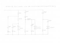
I think this is the one you are referring to. It is based on the original drivers and the Celestion revised (printed circuit) X-over design. The ESR simulating resistors shown are the values I used and were originally recommended by Alan.
The design is based on the use of low ESR metallized polypropylene caps like Solens (cheaper) or better sounding caps like Sonicap Gen 1 or ....... There is some support for using Solens for the 72uF caps and more expensive caps in the mid and tweeter circuit in order to reduce overall cost.
An externally hosted image should be here but it was not working when we last tested it.
Attachments
the crossover
Hi Bhu108,
both crossover schematics posted by Patrick Dixon and DennyG are correct,
but if you have the original Celestion HF2000 tweeters, then use DennyG's schematic.
For moderate sized capacitors of good audio quality for the tweeter and midrange filters
use the 250 volt rated ClarityCap ESA series now available from at least two UK sellers,
or the Sonicap 200 volt rated from the USA manufacturer's own web-site.
3.9uF substitutes for the 4uF; and the others can be 6uF or 6.2uF, and 24uF or 25uF.
For the caps in the bass filter the 250 volt rated Solens direct from solen.co
or 250 volt rated AXON from Parts ConneXion - The authority on hi-fi DIY parts and components are smaller than the 400 volt rated Jansons,
thus will fit on the boards more easily.
I have to go now - do you want me to list the other sellers ?
ESR simulating resistors for the improved crossover
Hello Kim,
The ESR simulating resistors used in my crossover were Mills MRA-5 (as recommended by Alan). They are available from Parts Connexion.
could someone please send me the information for the improved crossovers
Hello Kim,
The ESR simulating resistors used in my crossover were Mills MRA-5 (as recommended by Alan). They are available from Parts Connexion.
Correction to #846 , plus additions ...
I posted fast, didn't Proof-read, but logged off and left, and now I read a mistake in my last post !
For Solen, it is not .co , it is .ca - at: Untitled Document
Also, there are not currently any exact 72uF, nor 70uF, polypropylene capacitors made,
thus for 72uF, use 33uF + 39uF connected in Parallel, as in Patrick Dixon's schematic,
or use 36uF + 36Uf connected in Parallel as both Axon, and Solen in their 250 volt SA series, currently have 36uF.
If you do not want to connect two capacitors in Parallel,
then I recommend you use a single 75uF cap for the central position - connected to the junction of the two inductors,
and a 68uF cap for the output position - that is directly in Parallel with the woofer connection.
At least one 66 owner in this thread has reported results using 68uF and 75uF as above.
The Mills MRA-5 resistors are available from both Parts Connection and Sonicap's web-site.
Do use the 1 ohm and 1.5 ohm resistors even with 75uF and 68uF caps.
---
Hi DennyG,
I have given a bit more thought to that mismatched output of your mid-drivers, and will post about it soon.
Have you found any solution to it yourself ?
Last edited:
Matching the mids
No further progress from my end. Will be interested in your ideas Alan.
I have given a bit more thought to that mismatched output of your mid-drivers, and will post about it soon.
Have you found any solution to it yourself ?
No further progress from my end. Will be interested in your ideas Alan.
Hello again Alan. Thanks for your response. No, I haven’t done anything to the 66’s since my last post - apart from experimenting with those tweeters. As you say I probably didn’t give them a fair chance. I was mainly just playing around (you probably hate hearing that expression from novices) to see if I could detect a difference. What I have found is that high frequencies that my wife has no trouble hearing have completely gone for me. But even though I cannot hear them, in some cases, I can ‘sense’ them - a shimmering? The Hiqaphon’s I purchased were used OM2’s and (at the sellers suggestion) I put an L Pad on them ( 10 w 15ohm/5w .52 ohm wire wound resistors) to bring the sensitivity down to around the OM1 level.
Alan, please don’t misunderstand my motivation for wishing to mess with the Celestion’s midrange. With a well recorded CD my 66’s really do sound very good. With my present set-up it’s the best I’ve ever heard from them (second hand TL1 CD transport, Audio gd 7 DAC, TRAM linestage, 50 wpc monoblock push pull valve amps operating in triode mode) The midrange especially. I wouldn’t call them dynamic (unless played at high volume) but the smoothness of the 66’s allow hours of listening. The truth is I don’t need to change the midrange at all. But, I think I might like to experiment (not always a good thing I know but sometimes you have to try stuff – and it’s in my head now). I did find that thread I mentioned in my last post regarding fitting the Morel midrange to the 66’s. It was started in 2006 and is entitled “Celestion Ditton 66 Spares”. In it was a post from “Down in France” wanting to know a replacement for the MD500. SBA suggested a Morel EM1308 and alan-1-b (you) had this to say: “Morel EM 1308 will work in the 66 crossover if a resistor is connected in Parallel with it to reduce its middle of bandwidth impedance minimum to the same middle of band impedance as MD500. Use a 10 watt wire-wound resistor. You will have to measure the Impedance of EM 1308 across its useable bandwidth. Looking at the Morel specifications' plot it seems to be slightly higher than MD500, and that is good because it allows a single parallel resistor to be used”. It’s a pity Down in France never did get back in touch with his completed project (he was building new cabinets as well).
Anyway, as there hasn’t been any responses about the Morel I might just have a go. If I build complete new crossovers I can compare and, if I don’t like the Morel’s I’ll put them on Ebay. I can actually get a pair forwarded from Britain (Falcon Acoustics) for almost less than I can buy a single driver here from a local distributor (I’m conscious of shopping local but the distributor has to import them as required)
My plan is to search this thread and pull out stuff relevant to building a new crossover, including inductors, and then, have a go. I can be a guinea pig for those whose midrange’s have failed (but, who will trust my failing hearing?) As my wife and I are shortly to be away again (UK, Ireland and France) this is a job for the future.
Anyway, I hope I haven’t offended you.
Regards
Reggie
Hi, me again. I was just looking at the two crossover diagrams above and realised they were for the later model printed circuit board. According to the papers Celestion sent me the earlier "black faced" Celestion crossover had a total of 34 microfarads in the midrange, eg. 1 x 4uf, 1 x 6uf and 1 x 24uf . Not sure what the difference is but Bhu 108 might like to know. Also, they cascaded (is that the right description) a lot of little capacitors in the tweeter circuit.(6 x 1.5uf and 1 x 1uf). Anyway, I'll shut up now.
Reggie
Reggie
Listening versus Measuring
In #799 you state that with the Sudgen amp the sound is balanced, and with centre image centrally placed.
I think this you should trust ... your hearing, and in the room you usually listen to the speakers in.
In the other posts you have measured in a different room.
Unless you measured each speaker with it positioned in exactly the same position as the other speaker,
and with the non-measured speaker well out of the way so reflections from it cannot corrupt the measurement,
then these measurements may not be valid for showing differences.
Regarding the non-repeatability of the Right side tweeter measurement, it would have been wise to do a third measurement of it to compare,
and it would have been wise to do two of the Left side tweeter.
You will highly unlikely have identical shaped output across the full bandwidth of both tweeters,
thus the best you can hope for is a similar averaged output from both ... and which from the farfields it seems you do have,
except for the peak at about 17kHz, and that is relevant only to the very highest harmonics of Violin; Piccolo; Cymbals.
When you are listening, with the Sudgen amp connected, does the high treble sound balanced between Left and Right,
or does one side predominate a little ?
I could suggest adding a resistor to one tweeter, but unless you can hear significant difference there may be no need.
If you are not sure, then do the measurements again,
but if you are doing Nearfield then it is vital that the microphone be at precisely the same distance from and angle to one tweeter as it was to the other.
Tiny differences of distance and angle are magnified significantly with nearfield compared to very much less with farfield.
Regardless of whether an amplifier has a Balance control or not, some samples from the production batch are not exactly equal output from both channels.
Not every sample is tested for Balance by some manufacturers ... as strange as such may seem, especially for specialist manufacturers,
thus if you are considering buying a new amp listen in the shop to the sample you actually buy after you listen to the demonstration sample.
Yes, the salesman will warble on about Burn-in, but that should not change the Balance - Burn-in should only change the Tone.
Does your Sudgen have any failings compared to your other amplifiers ?
Hi Denny, I've read your Posts #799 on Page 80 and #803 and #807 on Page 81 again.No further progress from my end. Will be interested in your ideas Alan.
In #799 you state that with the Sudgen amp the sound is balanced, and with centre image centrally placed.
I think this you should trust ... your hearing, and in the room you usually listen to the speakers in.
In the other posts you have measured in a different room.
Unless you measured each speaker with it positioned in exactly the same position as the other speaker,
and with the non-measured speaker well out of the way so reflections from it cannot corrupt the measurement,
then these measurements may not be valid for showing differences.
Regarding the non-repeatability of the Right side tweeter measurement, it would have been wise to do a third measurement of it to compare,
and it would have been wise to do two of the Left side tweeter.
You will highly unlikely have identical shaped output across the full bandwidth of both tweeters,
thus the best you can hope for is a similar averaged output from both ... and which from the farfields it seems you do have,
except for the peak at about 17kHz, and that is relevant only to the very highest harmonics of Violin; Piccolo; Cymbals.
When you are listening, with the Sudgen amp connected, does the high treble sound balanced between Left and Right,
or does one side predominate a little ?
I could suggest adding a resistor to one tweeter, but unless you can hear significant difference there may be no need.
If you are not sure, then do the measurements again,
but if you are doing Nearfield then it is vital that the microphone be at precisely the same distance from and angle to one tweeter as it was to the other.
Tiny differences of distance and angle are magnified significantly with nearfield compared to very much less with farfield.
Regardless of whether an amplifier has a Balance control or not, some samples from the production batch are not exactly equal output from both channels.
Not every sample is tested for Balance by some manufacturers ... as strange as such may seem, especially for specialist manufacturers,
thus if you are considering buying a new amp listen in the shop to the sample you actually buy after you listen to the demonstration sample.
Yes, the salesman will warble on about Burn-in, but that should not change the Balance - Burn-in should only change the Tone.
Does your Sudgen have any failings compared to your other amplifiers ?
Last edited:
upgrades to either version of the 66
Hi Reggie,
first, wrt your Post #850, no you have not offended me !
I have re-read your original post from when you first joined this Thread.
I see you mentioned intending to get the crossover components "Professionally" installed.
Does this mean that you do not solder, or are not confident to do major soldering jobs ?
If so, then I will not describe interim auditioning modifications to you, because it will cost you a lot of money to have each modification soldered in and out.
You are quite entitled to try the Morel EM-1308 simply as experiment to satisfy your curiosity - that is valid DIY
- and even more-so if you post your auditioning results of them for us to read!
I have some additional plots from a sample of an EM-1308. They are very similar to the manufacturer's plots ... and that is good
... and also since I have moved I cannot find where I put those additional plots !
but I will find them eventually, and hopefully by the time you have bought samples,
so do post here later if you decide to proceed with EM-1308 as substitutions.
Given that your wife has good high frequency hearing, it is worthwhile to try the mod I suggested to listen to the 66s with only mid-domes and woofers in circuit,
and ask your wife to listen with her favorite recordings to hear if she can detect any significant mismatch between the mid-domes.
That is if you are happy to do the soldering necessary for that mod, as I explained it in the relevant post.
Regarding the 24uF//6uF summing to 30uF in the earlier 66s mids' filter:
Given the various plots that contributors have posted in this thread,
I think 30uF is too much for the MF500, and that 24uF, {or 25uF if buying from a brand that has 25 and not 24 }, is more suitable.
Further-more, given the plot from jt954 in #804 on Page 81, it seems that 24uF may be too much for his samples,
at least in conjunction with 1.8 ohms Series resistance there.
If his measurement is valid, I recommend trying 22uF and 1 ohm resistance.
For Electrical and Electronics' applications, the word "cascaded" usually means: connected in Series.
The small capacitors in the tweeter filter are connected in Parallel with each other to form two bunches of paralleled capacitors.
The old word used for Parallel in Electronics was Shunt.
You don't have to "shut up" - you can say whatever you wish to here, if you think such will assist readers.
If you still have the original capacitors in your 66s I think you should install new ones before you do more listening,
even if only for the input capacitor for the midrange filter if you decide to try listening without the tweeter,
because if that old capacitor starts to leak significantly the mid-driver will be damaged,
as similarly will the tweeter if any of its filters' caps leak significantly.
You could install a low price 22uF from a local seller, or Parallel pair of 10uFs or 12uFs in the mid-filter for now if you decide to try listening without the tweeters ,
and buy better caps later when you upgrade all the others.
The Shunt connected capacitors: 4uF in mids and 72uF in bass, if leaking will not damage the drivers,
but if they short-circuit excess current will be drawn from the amplifier, and it may be damaged.
So, post here what you have currently in your crossovers ?
You can buy some very good capacitors when you are in the UK, and also have some new inductors wound for the bass filter.
Ask here and I will advise further.
For the bass filter lower DC resistance inductors will allow better controlled bass response.
The inductors in the midrange and tweeter filters do not need to be changed {if not damaged},
because low DC resistance is not beneficial for the Shunt connected ones,
and the DC resistance is part of the Impedance of the circuit for the .34mH in the mids' filter.
Hi Reggie,
first, wrt your Post #850, no you have not offended me !
I have re-read your original post from when you first joined this Thread.
I see you mentioned intending to get the crossover components "Professionally" installed.
Does this mean that you do not solder, or are not confident to do major soldering jobs ?
If so, then I will not describe interim auditioning modifications to you, because it will cost you a lot of money to have each modification soldered in and out.
You are quite entitled to try the Morel EM-1308 simply as experiment to satisfy your curiosity - that is valid DIY
- and even more-so if you post your auditioning results of them for us to read!
I have some additional plots from a sample of an EM-1308. They are very similar to the manufacturer's plots ... and that is good
... and also since I have moved I cannot find where I put those additional plots !
but I will find them eventually, and hopefully by the time you have bought samples,
so do post here later if you decide to proceed with EM-1308 as substitutions.
Given that your wife has good high frequency hearing, it is worthwhile to try the mod I suggested to listen to the 66s with only mid-domes and woofers in circuit,
and ask your wife to listen with her favorite recordings to hear if she can detect any significant mismatch between the mid-domes.
That is if you are happy to do the soldering necessary for that mod, as I explained it in the relevant post.
Hi, me again.
I was just looking at the two crossover diagrams above and realised they were for the later model printed circuit board.
According to the papers Celestion sent me the earlier "black faced" Celestion crossover had a total of 34 microfarads in the midrange,
eg. 1 x 4uf, 1 x 6uf and 1 x 24uf .
Not sure what the difference is but Bhu 108 might like to know.
Also, they cascaded (is that the right description) a lot of little capacitors in the tweeter circuit.(6 x 1.5uf and 1 x 1uf).
Anyway, I'll shut up now. Reggie
Regarding the 24uF//6uF summing to 30uF in the earlier 66s mids' filter:
Given the various plots that contributors have posted in this thread,
I think 30uF is too much for the MF500, and that 24uF, {or 25uF if buying from a brand that has 25 and not 24 }, is more suitable.
Further-more, given the plot from jt954 in #804 on Page 81, it seems that 24uF may be too much for his samples,
at least in conjunction with 1.8 ohms Series resistance there.
If his measurement is valid, I recommend trying 22uF and 1 ohm resistance.
For Electrical and Electronics' applications, the word "cascaded" usually means: connected in Series.
The small capacitors in the tweeter filter are connected in Parallel with each other to form two bunches of paralleled capacitors.
The old word used for Parallel in Electronics was Shunt.
You don't have to "shut up" - you can say whatever you wish to here, if you think such will assist readers.
If you still have the original capacitors in your 66s I think you should install new ones before you do more listening,
even if only for the input capacitor for the midrange filter if you decide to try listening without the tweeter,
because if that old capacitor starts to leak significantly the mid-driver will be damaged,
as similarly will the tweeter if any of its filters' caps leak significantly.
You could install a low price 22uF from a local seller, or Parallel pair of 10uFs or 12uFs in the mid-filter for now if you decide to try listening without the tweeters ,
and buy better caps later when you upgrade all the others.
The Shunt connected capacitors: 4uF in mids and 72uF in bass, if leaking will not damage the drivers,
but if they short-circuit excess current will be drawn from the amplifier, and it may be damaged.
So, post here what you have currently in your crossovers ?
You can buy some very good capacitors when you are in the UK, and also have some new inductors wound for the bass filter.
Ask here and I will advise further.
For the bass filter lower DC resistance inductors will allow better controlled bass response.
The inductors in the midrange and tweeter filters do not need to be changed {if not damaged},
because low DC resistance is not beneficial for the Shunt connected ones,
and the DC resistance is part of the Impedance of the circuit for the .34mH in the mids' filter.
Last edited:
Listening versus Measuring
Hi Alan,
You are right about trusting hearing over measurements. There are so many variables including all those associated with testing. It would be nice to back up audible differences with test observations but I guess this is not always possible especially when one is new to speaker testing.
Your comments on repeating tests is heard loud and clear. My tests normally show excellent repeatability so I must have gotten lazy in not repeating the L tweeter test. I still don't know why the R tweeter repeat test was so different. I only noticed it when producing the final chart from the raw data and it was too late to repeat it as I'd packed up all the gear.
The little Sugden A28 has a reasonably balanced, musical, sound with the 66s and it is the best match for me at the moment at least until I can research more suitable amplifiers (maybe someone should start an 'Amplifiers for 66's' thread). It can seem a bit harsh in the upper frequencies sometimes with these speakers but this may be related to the amp itself or the source material more so than the speakers. Because it seems to match the speakers reasonably well I decided to spend some time and money the amp, with the assistance of diyAudio members. I'm currently replacing the RCA connectors as they were very poor from the start and introduce distortion at times. I'd also like to replace the source switches as they seem to introduce distortion sometimes. I also recently checked the power output (within spec) and the bias on this (basically) class A amp and discovered that the R channel had a bias 50% below spec. I'll consider other changes to the amp such as electro cap replacement after I put it back into service and have another listen.
As to the treble differences between L & R in the 66s. Others may notice this as my hearing at the highest frequencies is limited. My wife seems to be a lot more sensitive to upper freq issues than me so if you could suggest something like an additional resistor to the L tweeter to reduce the apparent imbalance I'll try it out.
dg
Hi Denny, I've read your Posts #799 on Page 80 and #803 and #807 on Page 81 again......
Hi Alan,
You are right about trusting hearing over measurements. There are so many variables including all those associated with testing. It would be nice to back up audible differences with test observations but I guess this is not always possible especially when one is new to speaker testing.
Your comments on repeating tests is heard loud and clear. My tests normally show excellent repeatability so I must have gotten lazy in not repeating the L tweeter test. I still don't know why the R tweeter repeat test was so different. I only noticed it when producing the final chart from the raw data and it was too late to repeat it as I'd packed up all the gear.
The little Sugden A28 has a reasonably balanced, musical, sound with the 66s and it is the best match for me at the moment at least until I can research more suitable amplifiers (maybe someone should start an 'Amplifiers for 66's' thread). It can seem a bit harsh in the upper frequencies sometimes with these speakers but this may be related to the amp itself or the source material more so than the speakers. Because it seems to match the speakers reasonably well I decided to spend some time and money the amp, with the assistance of diyAudio members. I'm currently replacing the RCA connectors as they were very poor from the start and introduce distortion at times. I'd also like to replace the source switches as they seem to introduce distortion sometimes. I also recently checked the power output (within spec) and the bias on this (basically) class A amp and discovered that the R channel had a bias 50% below spec. I'll consider other changes to the amp such as electro cap replacement after I put it back into service and have another listen.
As to the treble differences between L & R in the 66s. Others may notice this as my hearing at the highest frequencies is limited. My wife seems to be a lot more sensitive to upper freq issues than me so if you could suggest something like an additional resistor to the L tweeter to reduce the apparent imbalance I'll try it out.
dg
For reference only: may be useful to none diy'ers!
Hello Steve,
Yes, we have done exactly this several times for other customers - see
attached photo of our build-standard. However we do not supply Mills
resistors or Sonicap capacitors - previous customers have sourced these and
supplied them along with the original Ditton 66 inductors (we will measure
the value of each component before fitting to the new boards to ensure they
are OK and to obtain the best matched pairs). We build the new boards to
exactly the same size as originals and drill the fixing holes to enable the
boards to be fitted to the cabinet exactly as the originals. We supply the
Jantzen capacitors and the materials for the boards (tag-strips, screws,
ties, glue, wire etc.) As you can see there is quite a lot of manual work
involved. We test the finished crossovers on our Transfer Function Analyser
and provide frequency response printouts - so you can see the performance of
each of the filters and how well the crossovers are matched.
We can build and supply these for £300 for the pair including VAT and UK
shipping - assuming you supply the components as indicated above. We can
turn these around in 1 to 2 weeks depending upon our work-load at the time.
Best regards,
John
Audio Components (UK) Ltd
+44 (0)118 989 0151
srsanford posts a reply from John of Audio Components UK
There is no advantage either way whether the value is made up of 2 or just a
single capacitor. We can supply 72uF Polypropylene capacitors - these are
made by Clarity - they are similar in performance to the Jantzen CrossCaps
although they are physically larger. We purchased them last year as part of
a consignment of loudspeaker spares from RUARK (so they are marked 'Ruark')
these are priced at £20 each. We also have 24uF Clarity caps Priced at £7.50
each. For the 11uF we would supply a 10uF and 1uF in parallel £6.26 for the
2 values. For the 4uF the nearest standard value is 3.9uF which would be
closed enough (however if you want precisely 4uf we can supply 0.1uF to
connect in parallel) The 3.9uF is £2.67. the 0.1uF is £0.83. the 3.3uF is a
standard value and priced at £2.48. apart from the 72uF and 24uF, I have
quoted Jantzen CrossCaps which are good quality 400v Polys... these will be
more than suitable for the Ditton 66 (significantly better than original
components), however if you wanted to go up in quality, we can offer you
Jantenz Z-Cap Superior or Silver but these are several times the price of
the CrossCaps.
Presumable you are talking about the resistors in series with the 72uF
capacitors that were not in the original crossover? The DIY Audio team have
suggested inserting resistors in series with the capacitors to make them
nearer to the originals - I personally have a problem with this - let me
explain: the original 72uF capacitor were Bi-Polar Electrolytic types -
these are pretty crude capacitors and have 3 major problems (1) they are not
linear with frequency (in other words their capacitance value will be
different at different frequencies which can be a big problem in a filter!),
(2) they have a high ESR (Effective Series Resistance) this is an intrinsic
defect - an ideal capacitor would have zero ESR. There is a problem with ESR
in that it is unpredictable - you can have a batch of capacitors that will
all measure in spec for capacitance but they can all have different ESR
values - so it's impossible to say what the original ESR was. (3) both their
capacitance value and ESR will drift over time - which again is a problem
when using them in a filter circuit where you are relying on accurate
component values. Contrast all this with a modern polypropylene capacitor
that will have a very, very low ESR (something like 0.01 ohm or lower) and a
capacitance value that is both stable with frequency and will not drift over
time. So why would you want to (a) deliberately degrade the performance of a
high quality capacitor by adding a high ESR? and (b) if you did want to add
a particular resistance value to purposely dampen the Q (reduce the gradient
of the slope) of the filter, how do you know what the original ESR was?
The remaining resistors should be in circuit because they provide response
shaping (in case of mid-range) and attenuation in the case of the tweeter.
For your resistors (with due respect to you) there is no sonic advantage in
using Mills resistors in my opinion - the Jantzen Audio MOX resistors have
negligible inductance, are very accurate and will introduce no greater noise
or distortion than the Mills types that are significantly more expensive. We
have used both and there is no measurable or audible difference.
I hope this helps you.
Best regards,
John
Audio Components (UK) Ltd
+44 (0)118 989 0151
NOT Audio Components for vintage Celestions crossovers replacement !
Hi srsanford , and any other interested readers.
I strongly advise that owners of vintage Celestion speakers do NOT take them to John of Audio Components.
I have been in private correspondence with two Celestion 66 owners who had John of Audio Components design new crossovers for their 66s.
Both these owners are not happy with the results.
One of them has spent a lot of time attempting to get this John to remedy the very audible problems which John's Computer designed crossover has caused in his 66s,
but John refuses to refund him or credit him for exchange for replacement capacitors and inductors for the ones he sold him that are very audibly the wrong values.
The parts themselves are OK, it is the specific values that are wrong.
Computers cannot design crossovers, only humans can do that,
and to do it well the person needs to have experience with what can work and what can not work so that when he sees what the computer has presented him with he will know what will be audibly coherent and what will be audibly a mess.
I have seen two of John's crossover designs for Celestion 66s, and his modified crossover design for one of them.
Both will cause the speakers to sound very different to their original sound,
and both will cause the speakers to sound less good than the drivers are capable of with a better crossover design.
Also, both contain more components than is necessary.
The computer does not know that, because it can only respond to the specific instruction it is given.
A designer needs to know how to instruct a computer to get a design that can be audibly acceptable.
I do not know the criteria John uses when instructing his computer,
and I do not know the type of sound he prefers, however the owners of the speakers do not like the sound he has sold them.
If you wish, buy capacitors and inductors from Audio Components, but given what has been reported to me to date, and what I can see in these crossover designs,
I advise you to not buy design advice from Audio Components.
I have explained the reasons for adding the resistors in Series with some of the capacitors when substituting polypropylene types for the old electrolytics,
but it seems that John does not understand how this resistance keeps the crossover from being excessively resonant ... especially for the midrange filter.
Three-way loudspeakers are NOT easy to design - that is why there are so few good ones on the market, other than very expensive ones, and the messy sounding cheap ones.
The midrange filter is always audibly resonant, except when it is a 1st Order filter -{and that type is not suitable for the 66 drivers }-,
thus one has to design it very carefully so as to minimise the resonances.
John's computer designed crossover does not do that.
Computers cannot hear resonances. The designer has to be able to recognise when a midrange filter will be excessively resonant.
Using 10uF and 1uF in Parallel for 11uF will cause a sibilant sound - I have explained why earlier in this thread.
Better is to use a pair of 5.6uF in Parallel which sums to 11.2uF, and that is close enough, and possibly better if this is for use with a modification I posted earlier in this thread.
Do not expect most Components' sellers to know this, and I doubt that some of them listen to the results.
Others do not care, but simply sell the customer what they think is easiest to sell ... and when that is to owners of vintage loudspeakers
-{except for a very few models, such as LS3/5A}- they seem to assume the drivers will not be good enough for the owners to hear any problems that non-optimum component combinations will cause.
If the owner's drivers are in good condition and owner can hear the crossover problems the seller next tells him it is the fault of his old drivers not being as good as modern design drivers.
Some modern design drivers are not as good as those Celestion drivers, if the Celestion drivers are still in good condition.
An owner needs to know what is possible and what is not before he accepts any advice from a components' seller.
I am spending time advising about a very few vintage loudspeakers - only those that I know have sufficiently good drivers to be worth the particular components I recommend for restoring their crossovers.
--- --- --- --- ---
DennyG ,
if you are reading here, I will reply to your last post next time.
I was intending to reply today, but then I saw the Audio Components related posts which need an immediate comment on before anyone makes an expensive mistake.
66's
I used to drool over 66's ( 1971 ) . I stopped in Winchester one day and the guy thought I had some money and made efforts to sell me some . Funny things is Celestion couldn't give then away because Comet the discount store sold them . Years later a lady ( I think ,with her boyfriend also ) brought some to me to help her choose a system . She apologized for not being able to buy new . I don't remember what she bought ( Rotel / Rega ? ) .
I was gob smacked how good they were . Also the beauty of the engineering . Like a slightly more upbeat Spendor BC1 .
KEF Concertos were the obvious rival . Excellent also .
- Status
- This old topic is closed. If you want to reopen this topic, contact a moderator using the "Report Post" button.
- Home
- Loudspeakers
- Multi-Way
- Celestion 66 needs mid-range