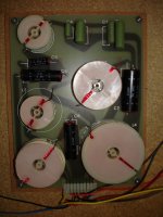
Confused as to the different components and a good replacement, brands? solen? daton? theta?$eek, what do you think Alan?
Also this is my week spot, are all those different types, black/green/yellow things just filter caps?
-3.3uf 160 ?
-2.2 uf/10/100?
24 mfd 50v i know this one...
Help
ToneDef2
Also this is my week spot, are all those different types, black/green/yellow things just filter caps?
-3.3uf 160 ?
-2.2 uf/10/100?
24 mfd 50v i know this one...
Help
ToneDef2
Ditton 66 - tweeters and cabinet top problem.
Given the reports by various owners about treble quality, and requests by some for recommendations for substitute tweeters, I will post here :-
First, look at the overhang of the top panel of the cabinet, yes it may look asthetically pleasing, but it is acoustically poor design in general, and more-so in this case as it is so close to the tweeter -{it looks about 2" away only in Grahame's photo in this thread}.
This will cause reflections of treble frequencies, delayed in time, thus various peaks and dips in the frequency response in the listening area.
Such would have been less of concern to Celestion when this speaker was first on the market because most buyers back then had not heard quality treble reproduction, but did expect loudspeakers to look good as furniture - especially at the price the Ditton 66 was.
Substituting a new dome tweeter will not solve the reflections problem, thus one should solve that first and listen to what the HF2000 tweeter is capable of, and then decide whether to try modern tweeters, or simply install better audio quality capacitors.
Obtain some double sided adhesive tape and some high-frequency sound absorbtive material - natural wool as in a felted woollen insulation batt is best, if not excessively compressed - there needs to be sufficient space between the fibres for sound to enter and vibrate the individual fibres.
Rockwool insulation batt or Fibreglass insulation batt of some grades is suitable also.
Next best is an Acoustic grade plastic foam, but only buy one for which the manufacturer has published absorbtion co-efficients, because not all expanded plastic foams absorb evenly, and some do not absorb much at all, and some partially reflect sound - particually part of the treble spectrum.
Bonded Acrylic or Acetate fibres, Dacron, etc ... do not absorb as well as the above listed materials, and there is only space for a thin strip between the tweeter's flange and the underside of the overhanging cabinet top.
Of course, for a simple trial one could roll up a woollen sock -{natural wool, not Polyester or Acrylic - those won't work well, if at all}- and use the double sided tape to secure it above the tweeter and to fully block the underside of that overhang, then listen !
For absorbtion the strip of a batt must be cut and placed so that an open cut edge is facing the tweeter, as the sealed or semi-sealed sides of most batts do not absorb treble frequencies well, and some sealed types reflect treble.
Remember, those batts are designed to absorb heat and/or midrange sound frequencies.
There looks to be space for only a about a 1" wide strip between the underhang and the egde of the tweeter flange.
For High Fidelity sound, it is not a good practice for a thick absorbtive to be placed at the edge of the tweeter dome itself, thus place it only to the edge of the tweeter's mounting plate, OR, cut a taper across about 1" of a 2" thick strip - that is, extend it to between 1/4" to 1/2" away from the dome but with it cut tapering away from the dome, but with still at least 1" thickness at outer part under the underside of that overhang to get sufficient absorbtion under the outer edge of the overhang.
Cut the strip to extend the full width of the baffle.
If you want this to work with the Grille frames on, then you will have to think of a way to acheive that - perhaps cut a taper under the top edge of the grille frame and stick the absorbtive to that, and also stick strips down the top parts of both insides of the sides of the grille frame down to a few inches below the level of the midrange dome.
2" thick would fit there, and absorb well enough to give less spikey or rough edged sound from treble and upper mid frequencies.
____________________________________________________
For substitute tweeters, if still wanted after the above, and new capacitors have been installed, do you want tweeters with 3 screw holes such as the originals are ?
Or, will you tolerate the now more common 4 or 5, etc ... screw hole tweeters and drill new holes in your 66s baffles ?
Yes, there are some 3 hole tweeters still available, but you will have to measure the spacings of the Celestion tweeters' holes and look at the current manufacturers' data to see if their spacings match.
Look at the data for the Hiquphon OW1 tweeter, the SEAS 19 series tweeters as these are good quality 3 hole types.
I do not know the exact Voltage Sensitivity{Efficiency} of the Celestion HF2000 -{does any reader of this ? - please post if you do}.
I estimate it would be about 89dB/w/m, and that is the figure for the OW1 and a few of the SEAS 19 series models.
____________________________________________________
tonedef2,
by "daton", I think you meant to type "Dayton" ?
and by $eek, I think that is your reaction to the price of the Thetas !
I will email you to discuss capacitors. I have posted the other information above for any other Forum members who may be following this thread now or in the future.
regards,
Just a quick update guys,
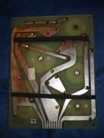
I had a closer look at the installed crossover, even managed to remove it a get a picture of the traces on the back which I can post when I have time.
I'll also try and make a schematic using EAGLE (light) software, and spend some time working out if the topology is the same as for the point-to-point wired version.
At least I know the build date now. Undid 4 hex nuts at corners of crossover to remove and get view of back of circuit board.
Behind board was stamped "Nov 22 1977" so ~30 Years then.
New text values for the "Green" capacitors (C1, C2, C3, C4) are
C1+2 and C3+4 are in parallel on the traces.
C1
EIRE
4.7
160 (V)
C2
EIRE
1.5 uF
160V
C1+C2 = 4.7 + 1.5 = 6.2 uF
C3
EIRE
3.3uF
160V
C4
.68
160
C3+C4 = 3.3 + .68 = 3.98uF
Which looks like someone was trying to approximate these values (6, 4) with newer(?) capacitors on the point-to-point crossover.
I'm getting up to speed, learning all about crossovers + electronics.
If I've pattern matched (it looks the same as ...) the crossover schematic correctly with here
http://www.bcae1.com/xoorder.htm
The Tweeter has a Third order high pass ( 2 C's in series , 1 L in parallel )
The Sub has a fourth order Low pass ( 2L's in series , 2 C's in parallel)
Which I guess leaves a band pass filter for the Mid - I might need some help on that.
I plotted the schematic by hand - matching it to the layout on the point to point board - I'll do the same for the Circuit board version.
There is a local electronics shop - if they are friendly, I may be able to get them to measure the inductance of the inductors - so we'll know what their values are - and see how the capacitors have changed from their printed values.
Given the values - we should be able to derive / simulate the cross over points / slopes.
I've been loaned some (sound) measurement equipment - so with a bit of luck I may also be able to plot some frequency response graphs!
It will be interesting to see the before + after results.
Thanks for all your help guys - we should be able to get some definitive info together for all the other '66 owners out there.
tonedef2 - you mentioned spikes - what type did you use, and how did you affix them?
Grahame you are all over this crossover, i just dont have the time to learn it right now....new job lots there to learn.
It will be very interesting to see your results.
Spikes were just the standard wood anchore type...drill hole, slip in threaded anchore and screw in spiked feet, picked em up at Parts Express.
Alan, I'm using the tweeter rings that surround the whole tweeter, do you think i will gain by using your defraction method you mentioned above?
ToneDef2
Thanks and more ...
Thankyou for posting all that information Grahame ! , and whatever else you can post and have measured may be helpful also for getting the best from 66s with modifications , etc ...
The Inductors are probably the values that are printed on the layout you posted previously, and given there in microhenries, = uH, instead of the more usual millihenries, = mH.
Eg:- 547uH = .547mH
and 1163uH = 1.163mH
etc .... , as this does calculate OK for the 4th order filter on the woofer, for what seems to be a 4ohm woofer with 1.359mH ; 1.358mH ; 72uF ; 72uF , BUT, do not expect to get these values from a Standard 3-way x-over calculator for any textbook filter name, because this specific electrical filter has been adjusted to take into account the woofer's rising impedance at 500 Hz, and the possible rising frequency response from about 400 to 800 Hz - typical of 12" drivers.
Similarly for the mids high-pass and low-pass filter arms. Those are electrically 2nd order, but there will be roll-off at both ends of the MD500's response, thus the actual filter slopes in the loudspeaker could be 3rd order or 4th order - I'll guess at 4th order Hi-pass and 3rd order Lo-pass, but I could be mistaken, and they couild both be in-between slopes !
Especially the Lo-pass, because the Hi-pass to the tweeter is slightly unusual.
Yes, it is electrically 3rd order, but 1.163mH is much larger than would be used into a simple resistive load for 5kHz with those capacitor values.
The HF2000 will have a higher impedance in the band a little below its cross-over point, and much higher impedance at its Fs, which is probably about 1 1/2 or 2 octaves below cross-over, but does affect the electrical filter, thus the larger inductor may be intended to compensate for that, IF my estimate is correct that those numbers are the inductor values.
You posted the MD500s measured 6.7 and 6.9 ohms DC resistance, and that is about right for a nominal 8 ohm driver.
The woofers are apparently 4 ohm - if so they'd measure about 3.5 ohm DC.
I think the tweeters are 8 ohm, thus would measure about the same resistance as the MD500s - if you have time, measure the DC resistance of both tweeters and both woofers and post.
If you can disconnect and measure the individual driver's frequency responses with no cross-over connected, as well as each with cross-over connected and post both the without and the with, then we can solve this cross-over, and maybe make a mod. to it that could improve its High-Fidelity.
EIRE is an old brand of capacitor, and those are probably Polyester or Metalized Polyester types - not great for sound, and can start to leak when very old, especially if simple Polyester, but they're not as risky as the black electrolytic caps which should be replaced now to avoid undue risk.
The inductors are unlikely to be faulty. Measure each for DC resistance when you have the drivers all disconnected, and see if they are close to the ohm values shown on that schematic you posted.
As to whether to use 6uF or 6.2uF depends on whether one intends to change the tweeters, and what the frequency response plots ot the HF2000s look like without the cross-overs connected.
Try a measurement of the HF2000 with the 6uF x-over and another with the 6.2uF x-over.
I suggest leave those 6 and 6.2 as is and try the anti-reflection ideas I posted, then you can substitute your x-overs and hear the effect of the different value caps to the tweeters more clearly.
____________________________________________________
tonedef2,
the tweeter rings you are using, how far in front of the baffle do they extend - thickness above baffle ?
And, how wide are they from inside of ring to outside of ring ?
regards,
Hi Alan,
This is where i picked them up...
AIG System Tweaks
AIG Imagers:
http://www.audio-ideas.com/tweaks.html
IMAGERS ARE BACK!
Andrew Marshall's original Imager design was quite straightforward: a circular neoprene ring that surrounded the tweeter and absorbed energy that would otherwise have been radiated along the speaker baffle and re-radiated milliseconds later at the listener when it reached the edge. The design was sound, and 5000 pairs were sold with not one consumer complaint or return, and a plethora of praise for the improvements wrought with normal direct radiating box speaker designs. Speakers just imaged better, with more depth! (At right you'll see the new, oval Imager)
However, it was pointed out by a major Canadian speaker designer that reflections off the inside of the Neoprene ring caused slight peaks and dips in frequency response (2 dB or less) around 10 kHz. The solution? Make the new Imagers oval in shape, so that the frequency of these minor reflections would be staggered between 8 and 12 kHz, and therefore unmeasurable in their interaction with the directly radiated sound of the tweeter
That's just what we did, made them oval in shape, but there's more! Marshall researched the available Neoprene compounds, and found one that was softer and more absorptive in the audio frequency range, and therefore did not reflect as much energy. The result is a much improved version of our famous Imagers: Imagers II. You can have the wider part of the oval at the sides, or top, it doesn't matter. Self-adhesive, Imagers II are easy to fit to your speakers, and need never be removed (if you do decide to remove them the special adhesive WILL NOT leave any kind of residue on your speakers). They'll deepen the soundstage and control side-wall reflections while also eliminating baffle diffraction.
Bafflegab? Hey, it's good physics: the more your speakers are a point source, the better they'll image. And that's the truth! Imagers II are priced at $9.99 a set, but if you order 2 sets, they're only $15, and 3 sets (which should cover a home theatre system with a spare) are only $19.99
ToneDef2
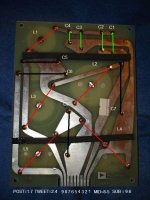
Mirroring the back of the PCB, comparing it to the front, and some work in MS Paint gives us the following
Green = Green Capacitors C1, C2, C3, C4
Black = Black Capacitors C5, C6, C7, C8
Red = Inductors L1, L2, L3, L4, L5
Post= inputs 1-7
Tweeter = inputs 2-4
Mid = inputs 8-5
Sub = inputs 9-6
Using Alan's units/values we have
C1=4.7uF
C2=1.5uF
C3=3.3uF
C4=0.68uF
C5=4uF
C6=72uF
C7=24uF
C8=72uF
L1=1.163mH
L2=1.358mH
L3=0.547mH
L4=1.359mH
L5=1.358mH
Hopefully we should get the real values for the inductors soon.
Alan - are there any issues I should be aware of when running the frequency response tests - I think it runs sweep tones / impulses via the inputs - 20-20KHz - I think - so that should be OK with the crossover in place.
If I run the sweeps directly to the drivers without the crossovers ( if I can wire it up like that) should I restrict the frequency range I subject each of the drivers to?
e.g. MD 500 says .5-5KHz on back
so I'd guess 20-500 for the sub
500-5KHz for the MD500
5KHz - 20KHz for the HF2000's
I won't try anything until I hear from you and have read the manuals on the measurement gear.
Attachments
I Have Measurements from the point to point crossover.
Thanks to those nice folks at Electronics Plus
and an LRC meter we have the following measurements of the inductors - taken when the inductors where isolated from the rest of the circuit - by means of cutting the wires
The Names are from the PCB layout - The number in brackets is the text on the outside of the inductor - and the measurement is from the LRC meter.
L1=(1163)=0.15mH
L2=(1358)=2.16mH
L3=(547)=0.33mH
L4=(1359=3.68mH
L5=(1358)=2.16mH
Alan - does this look right? - now we have all the values can we determine the crossover points + slope values?
Is there any software where I can plug in the numbers?
I can now add the resistance values form my multi meter -
all values are in ohms
L1=(1163)=0.15mH=0.6R
L2=(1358)=2.16mH=1.3R
L3=(547)=0.33mH=0.6R
L4=(1359=3.68mH=1.3R
L5=(1358)=2.16mH=1.5R
I've had a look at the Capacitors at - parts express
Lots of choice, and lots of prices! - what would you recommend,
in terms of best value for the money - good audio qualities, but not silly money, please
L1 look funny to me but im very interested in what Allen thinks, your doing great and sounds like we are going to make our beloved Celestions really sing......
I have not dealt with the top lip diffraction yet, but will post my findings soon, my thoughts so far is we may solve some key problems with baffle and phasing and with the addition of quality caps should give us a very nice recipe..........i think this tweeter will work great after that.
Pete
I have not dealt with the top lip diffraction yet, but will post my findings soon, my thoughts so far is we may solve some key problems with baffle and phasing and with the addition of quality caps should give us a very nice recipe..........i think this tweeter will work great after that.
Pete
Sorry, but a delay ...
Hi guys,
Excellent that you've got the Inductor values Grahame !
Sorry, but I am working in a country area town where I do not have computer access, thus I will not be able to reply to your several posts for at least 6 days, or 7 days from today.
But, don't worry, you have posted plenty for me to think about, thus I will reply !
tonedef2,
I suppose you have heard a difference with those ovals in place ?
Have you tried them in both their standing on end vertical orientation, and lying on side horozontal orientation ?
Given the proximity to the top of cabinet overhang, I'd expect the lying on side horozontal to work better, but what have you found to be the case ?
If you're undecided about which orientation you prefer, try them also at a tilt of 45 degrees -{falling over !}- but yes, I am serious, such is worth a try.
Note, the mentioned 10kHz effect of the original rings, and now spread across 8kHz - 12kHz for the ovals, that is they partially reflect sound !
I'd have made them from soft wool felt !!
regards,
Hi Allen & Grahame
Yes Allen I did notice a positive difference, perhaps described initially as reduced attenuation / less noise, but we all know it can be better (side note> this mid dome is so wonderful in it’s very wide sweet spot). Question> did you mean that this ring will reflect on the inner surface???? It’s very porous on that side... or absorb? Should I go with an audio type woolen felt material instead?
The instructions for the ovals say this up/down orientation is best, not considering the lip of course.
Grahame your really tearing into this just like I would love to, time permitting...let me know if you need any of my worthless help.
Grahame was I correct in L1 being way out?
Ok Allen, will wait till you get a connection.
ToneDef2 / Pete
I can wait for Alan to get back in the loop.
the L1-L5 names are from the PCB layout,
I'd be particularly interested in recommendations for brands of capacitors and tolerances.
The inductor measurements were what they were - I took several readings just to be sure.
Given we now have
1) The crossover topology
2) The values of the components in the crossover (L + C)
we should be able to stick the values into some software (suggestions please!) and see what the designers were attempting to do.
Also - this should show us the effect of changing the capacitor values
(6.2 -> 6 , 3.98 ->4) and if this is a good or bad thing - or irrelevant as the actual values would have a 20/10/5/1% tolerance anyway .
Pete - I'd be interested in your findings re: the acoustic treatment for the tweeter - then I can just follow your lead.
I'll see if I can get the DC resistance values of the speakers - disconnected - (tweeter, mid and sub) to complete the set of measurements.
I'd also be interested if Alan knows of anybody else whose expertise would benefit this thread.
Pete - does your crossover look like my PCB - its behind the Sub.
Computer availability is brief today ...
0.15mH for an inductor in that position of the 3rd order electrical filter at about 5kHz is a size I would expect.
Grahame and Pete :-
When you have time, measure and post the DC resistances for both your tweeters, and I'll comment some more on that filter.
Similarly for the 4th order electrical filter to the woofer, when you have time measure both woofers' DC resistances and post.
The DC resistances of both L4 and L5 are significant in the behavior of this filter, and now we know those, thus need the value for the woofer itself.
____________________________________________________
The E.S.R. values of the electrolytic capacitors will be significant also, and likely need duplicating when replacing with the much lower ESR polypropylene capacitors, especially for the 72uF cap that is in direct parallel with the woofer, and perhaps for the other 72uF, and less likely for the 24uF -{which will have a lower ESR anyway}, and highly unlikely to be necessary for the 4uF black cap.
E.S.R. = Equivalent Series Resistance
This is not easy to measure, but can be estimated from other measurements.
I can explain how to do this, but you will need some specific test equipment, and a Standard - a known value resistor - for comparative voltage measurements.
Do you both have a 1%, or closer, Tolerance resistor that is of any value between about 6 ohms <---> 10 ohms ?
In 2 watt would be best, but hard to obtain ; 1 watt is OK, but even if you can only buy a 1/2 watt 1% tolerance resistor, it can be used to check the accuracy of your multimeters' ohm ranges, and then a 2% or 5% resistor in larger wattage can be measured and used for the Standard.
Buy 2 in case one gets broken.
Vishay VTA52 series is 1watt in 0.5% tolerance and is available in 10 ohm for about $6.50 in the USA.
There are much cheaper available in 1/2 watt in 1%, and probably in 0.5%.
____________________________________________________
For the AC voltage ranges of your multimeters, what does the owners' manuals list for :-
Accuracy ?
Frequency Response ?
There may be different Accuracy specifications for different frequency bands.
Are your meters "True RMS" for the AC ranges ?
OR is this not specified ?
What is the Digits' display ?
Eg:- 4 1/2 digits' display shows each range to a maximum of 1999.
And 3 3/4 digits' display shows each range to a maximum of 399.
____________________________________________________
Do you have Audio Frequency sweep oscillators ?
and their Wave type ? -{usually are in Sine Wave, some have Square Wave also}.
OR, do you have CDs with fixed, listed Frequencies in Sine Waves ?
If so, please list the available frequencies ..?..
____________________________________________________
All the above can be used to do measurements to be able to estimate the ESR values of electrolytic capacitors ; the pass-band Impedances of the speaker drivers - and this we do need to know if considering whether alternate tweeters would substitute for HF2000 ; the Fs's, and the magnitudes of Impedance at each, of the HF2000 and the MD500 - for if you want to know more about the cross-over slopes, and whether it may be worth deciding between 6uF and 6.2uF for that tweeter filter's cap., and some other matters ...
____________________________________________________
Grahame, I'll post about the safe-to-measure bandwidths for the HF2000s and MD500s as soon as I have time to,
and also about brands for capacitors, and the other things you asked,
hopefully next week-end.
regards,
tonedef2 said:L1 look funny to me but im very interested in what Allen thinks,
Pete
0.15mH for an inductor in that position of the 3rd order electrical filter at about 5kHz is a size I would expect.
Grahame and Pete :-
When you have time, measure and post the DC resistances for both your tweeters, and I'll comment some more on that filter.
Similarly for the 4th order electrical filter to the woofer, when you have time measure both woofers' DC resistances and post.
The DC resistances of both L4 and L5 are significant in the behavior of this filter, and now we know those, thus need the value for the woofer itself.
____________________________________________________
The E.S.R. values of the electrolytic capacitors will be significant also, and likely need duplicating when replacing with the much lower ESR polypropylene capacitors, especially for the 72uF cap that is in direct parallel with the woofer, and perhaps for the other 72uF, and less likely for the 24uF -{which will have a lower ESR anyway}, and highly unlikely to be necessary for the 4uF black cap.
E.S.R. = Equivalent Series Resistance
This is not easy to measure, but can be estimated from other measurements.
I can explain how to do this, but you will need some specific test equipment, and a Standard - a known value resistor - for comparative voltage measurements.
Do you both have a 1%, or closer, Tolerance resistor that is of any value between about 6 ohms <---> 10 ohms ?
In 2 watt would be best, but hard to obtain ; 1 watt is OK, but even if you can only buy a 1/2 watt 1% tolerance resistor, it can be used to check the accuracy of your multimeters' ohm ranges, and then a 2% or 5% resistor in larger wattage can be measured and used for the Standard.
Buy 2 in case one gets broken.
Vishay VTA52 series is 1watt in 0.5% tolerance and is available in 10 ohm for about $6.50 in the USA.
There are much cheaper available in 1/2 watt in 1%, and probably in 0.5%.
____________________________________________________
For the AC voltage ranges of your multimeters, what does the owners' manuals list for :-
Accuracy ?
Frequency Response ?
There may be different Accuracy specifications for different frequency bands.
Are your meters "True RMS" for the AC ranges ?
OR is this not specified ?
What is the Digits' display ?
Eg:- 4 1/2 digits' display shows each range to a maximum of 1999.
And 3 3/4 digits' display shows each range to a maximum of 399.
____________________________________________________
Do you have Audio Frequency sweep oscillators ?
and their Wave type ? -{usually are in Sine Wave, some have Square Wave also}.
OR, do you have CDs with fixed, listed Frequencies in Sine Waves ?
If so, please list the available frequencies ..?..
____________________________________________________
All the above can be used to do measurements to be able to estimate the ESR values of electrolytic capacitors ; the pass-band Impedances of the speaker drivers - and this we do need to know if considering whether alternate tweeters would substitute for HF2000 ; the Fs's, and the magnitudes of Impedance at each, of the HF2000 and the MD500 - for if you want to know more about the cross-over slopes, and whether it may be worth deciding between 6uF and 6.2uF for that tweeter filter's cap., and some other matters ...
____________________________________________________
Grahame, I'll post about the safe-to-measure bandwidths for the HF2000s and MD500s as soon as I have time to,
and also about brands for capacitors, and the other things you asked,
hopefully next week-end.
regards,
Diffraction and Reflections.
Well, given the Designer's, or, Manufacturer's comments about their measured 10kHz effect - and then 8kHz <--> 12kHz effect for the oval shape - there is obviously either, or both, diffraction or reflection occurring from either the inside edge or the top surface of the oval.
A foam rubber is never fully porous - such usually have some sealed cells - visible as small flat sufaces.
Inspect the top and inside of the ovals with a strong magnifying glass.
Post whether you can see any very small flat surfaces in the foam, then we will know whether these ovals partially reflect, or only diffract sound waves.
Even small flat surfaces are sufficient to cause some reflections of the short wave-lengths' high treble frequencies, and,
any mass - even a porous one - has some acoustic impedance that is different to air, thus there will be some diffraction of part of the bandwidth of sound when the sound waves pass the junctions of air-foam-air.
Try the rolled up woollen sock under top of baffle lip idea I described, both with and without the ovals in place, and listen for preferences ...
Given the audio qualities of those MD500s is why we are continuing to pursue this restorations/modifications topic to such degree - I think they are worth this.
regards,
tonedef2 said:
Yes Allen I did notice a positive difference, perhaps described initially as reduced attenuation / less noise, but we all know it can be better (side note> this mid dome is so wonderful in it’s very wide sweet spot). Question> did you mean that this ring will reflect on the inner surface???? It’s very porous on that side... or absorb? Should I go with an audio type woolen felt material instead?
The instructions for the ovals say this up/down orientation is best, not considering the lip of course.
ToneDef2 / Pete
Well, given the Designer's, or, Manufacturer's comments about their measured 10kHz effect - and then 8kHz <--> 12kHz effect for the oval shape - there is obviously either, or both, diffraction or reflection occurring from either the inside edge or the top surface of the oval.
A foam rubber is never fully porous - such usually have some sealed cells - visible as small flat sufaces.
Inspect the top and inside of the ovals with a strong magnifying glass.
Post whether you can see any very small flat surfaces in the foam, then we will know whether these ovals partially reflect, or only diffract sound waves.
Even small flat surfaces are sufficient to cause some reflections of the short wave-lengths' high treble frequencies, and,
any mass - even a porous one - has some acoustic impedance that is different to air, thus there will be some diffraction of part of the bandwidth of sound when the sound waves pass the junctions of air-foam-air.
Try the rolled up woollen sock under top of baffle lip idea I described, both with and without the ovals in place, and listen for preferences ...
Given the audio qualities of those MD500s is why we are continuing to pursue this restorations/modifications topic to such degree - I think they are worth this.
regards,
Clarification of a recent post, and of an earlier ...
By "Standard", above, I mean as a Reference.
Though, if you don't mind working within the accuracy limits of the Resistance ranges of your multimeters, then you can simply use the 2% Dayton resistors that Parts Express sell for loudspeaker cross-overs.
alan-1-b said:
I can explain how to do this, but you will need some specific test equipment, and a Standard - a known value resistor - for comparative voltage measurements.
,
By "Standard", above, I mean as a Reference.
Though, if you don't mind working within the accuracy limits of the Resistance ranges of your multimeters, then you can simply use the 2% Dayton resistors that Parts Express sell for loudspeaker cross-overs.
Made a mistake - now very angry !
Sorry, I have just now accidentally erased most of a very long post - I can't believe this, but I did !
It was part of the above appearing post, but only that part remained - I don't know how I did it !?!
I have no time left to do it again now, thus will have to leave till next weekend.
I regret this,
real drivers and cross-over considerations.
Back again !
In regard to matters raised about filter slopes and software for calculating cross-over components values :-
The text book formulae ; on-line calculators ; and various software for cross-over filters all require a constant Impedance across the driver's useable frequency bandwidth and a flat Frequency Response for at least 2 octaves past the cross-over frequency.
Most drivers, including the 3 active drivers in the Ditton 66, do not have constant impedance nor flat frequency response in some otherwise useable areas of their bandwidth.
There seem to be some software types that one can enter variable impedance and non-flat frequency response data into, but I am not familiar with those.
I cannot find frequency response nor impedance plots for any of the 66's drivers, so I will give examples of some similar drivers :-
go to www.celestion.com
click on Guitar Loudspeakers
look down the the left-side column and click on "Ask Dr Decibel"
scroll down the page to "Archive Specifications" and click on "G12M-70"
see the frequency response -{in red}- has a raised plateau in the 850Hz - 1kHz region, then a notch at about 1.3kHz, then a large peak centered on about 2.5kHz.
this is characteristic for 12" paper cones with a slightly ourved profile.
the woofer in the 66 will have similar, though possibly in slightly different areas of its useable bandwidth, and the upper midrange peak may not be as large - all 3 depend on cone mass ; cone stiffness ; voice-coil diameter, {as well as cone diameter}.
see the impedance plot -{in blue}- on the same graph.
see how it changes across the frequency bandwidth of the driver.
its minimum - in the 200Hz - 400Hz area is the Nominal Impedance of the driver, and this is usually about 20% larger than the driver's DC resistance which your multimeter measures.
the impedance is higher than the nominal value in the cross-over region if one was considering a 500Hz crossover freq. and the need for a constant impedance to beyond 1kHz so that the electrical filter will work as designed to.
Print or Store the G12M-70 plots so you can look at them beside the other plots I'll list below:-
go to www.moreleurope.com
click on "Drivers", and then at the bottom of the page click on "Click here for products overview"
click on 'midrange" and open the "product information sheet" for the MDM 55 dome.
see the Impedance Magnitude plot - large changes across the frequency bandwidth.
the hump at about 380Hz is the Fs for this driver.
As it is quite high, it is not highly damped, thus one cannot use this area of the frequency spectrum for any significant output level a it will simply distort, and probably damage the driver as it likely has a limited excursion also.
I do not know the Fs of the Celestion MD500, but it may be as high in frequency as 500Hz, however from tonedef2's description it seems it is very well damped, and it may have sufficient excursion capacity to reproduce significant output at its Fs -{woofers usually do, and some cone midranges do, but rarely do dome midranges and tweeters}.
see the "Sensitivity Magnitude" plot -{this is the frequency response}- and where the response rolls off at a slow rate slope below 1kHz, and where it rolls off at a higher slope rate above 6kHz.
this is typical of mid-domes of that size, and in this one it is very well controlled.
Print or Store those plots for comparison with the next:-
For a less well engineered upper end roll-off, but quite good lower end roll-off, AND, less change of impedance magnitude, go to:-
www.tymphany.com , and under "Products" cllick on "Peerless" in the left-side column, then on "midranges" and open the file for the D75MX-41-08 , and Print or Store to compare the plots for it to those of the Morel MDM 55.
I do not know the rate of roll-off slopes for the Celestion MD500, but as it has 2nd order electrical filters I think it will likely have moderate slope roll-offs at both its low and high ends.
next look at Peerless tweeters:-
look at APL25SC15-04, it has its Fs at about 1.5kHz, which is approximately where I think the Celestion HF2000's Fs will be, or it may be slightly higher in frequency.
see the Fs is not well damped, and this is also indicated by the hump in its frequency response in the region just above its Fs.
look at BC25SC15-04, it has a slightly better damped Fs -{at 1.32kHz}- and a flatter frequency response.
Print or Store the plots for the BC25SC15-04, then place 3 of these plots side-by-side :-
the G12M-70 - one of the mid-domes - the BC25SC1-04 tweeter, and try to imagine how these 3 can be crossed over at useable points in the bandwidth of the mid-dome, and then with the other mid-dome.
In theory, one has to make the impedance constant around the cross-over regions - that is usually done with resistors plus either or both capacitors or inductors - AND make the frequency resp. flat, which is possible only with the woofer in this example, and is done with some or all of resistors; capacitors; inductors.
In practice -{in most cases}- one can combine the functions of the required components for the electrical filters and the required components for the impedance and frequency resp. compensation components, and use less components, BUT these will be different values to what is given for simply the electrical filters' slopes.
This is what Celestion seem to have done.
For electrical filter on the woofer Celestion have used a 4th order slope, AND, this will include a larger than expected value capacitor for the cap. parallel closest to the woofer, to compensate for the rising impedance magnitude in the cross-over region.
That cap. may part compensate for the rising frequency resp. magnitude also, as likely does the slightly larger than expected inductor beside it -{2.16mH}.
The other cap. and induct. seem to be what I would expect for approximtely 500Hz cross-over for a driver impedance plus inductors' DC resistances to total of about 7.5ohm, -{but for some cross-overs the other cap. and/or induct. may be changed also}.
As there are no resistors used, I think the highish E.S.R. - typical of electrolytic caps, especially of that vintage, may be incorporated into the cross-over design.
The MD500 wll have its own roll-off slopes, thus Celestion need use only lower order electrical filters there to achieve total roll-off rates of 4th Order, and the cap. and induct. values seem to have been chosen to compensate for a non-constant impedance.
For the HF2000, at least one of the caps will have to be different than exected to compensate for the impedance hump at the driver's Fs, and to compensate IF a non-flat freq. resp. at least 1 octave both above and below the cross-over frequency.
As the inductor is about the value one would expect for a nominal 7ohm tweeter -{is it ?}- , I think the HF2000 will not have required a lot of compensation cicuitry, but as Celestion have used a Reversed Polarity connection for the tweeter I am wondering whether this is result of using less cross-over components than would be required for a Like Polarity connection for the tweeter.
All this is why it would be useful to have some measurements of at least the HF2000 if one is considering substituting another tweeter.
For the MD500 some measurements would be useful also to assist in integrating it with a different tweeter.
For both these drivers some measurements would be useful if one wants to know which option of the different capacitor values to choose, but it is not absolutely necessary.
I have run out of time and will have to go now as I am very late.
More next week.
Post some comments if this is, or is not, in the direction either of you wish to go !
- Status
- This old topic is closed. If you want to reopen this topic, contact a moderator using the "Report Post" button.
- Home
- Loudspeakers
- Multi-Way
- Celestion 66 needs mid-range