If I looked up correctly the Bob Smith approach is to reduce / avoid cavity resonance in the phase plug.
If I understood Earl in one of his early postings right, Bob Smith wasn't after flat wave front at the exit of compression driver though.
From my little experience with horns, I already know that flat wave front injection into a horn is pretty high on my list.
Anybody to comment, compare or relate sonics of real world driver to the design goals of "flat wave front" generation versus "Bob Smith correct" ?
Michael
Hello Sven,
Do you have any pictures with your system? Or at least a more detailed description? I think I've only seen a small reference to it a couple of posts ago.
Regarding Michael's comment:
Is there any way to check for flat wave emission from a Bob Smith phase-plug? It might as well achieve both purposes, flat wave and avoidance of cavity resonance?
Regarding the last point, I remember Dr. Geddes also being carefull to watch for drivers not exhibiting cavity resonances. I think that's one of the reasons he regards modern B&C drivers as oposed to older designs.
Given the spheric shape of a compression driver membrane - with quite different distances a wave has to travel along annular slits to finally reach exit - its hard to believe a flat wave front ever could happen with such a design.
Don't know enough about the tangerine shape tho..
Pix of TAD compression driver cut in half from Patrick Bateman:
http://www.diyaudio.com/forums/multi-way/103872-geddes-waveguides-76.html#post2049183
On the other hand *if* the horn can handle the wave front shape injected - possibly no big deal...
Hence I asked for first hand experience of the connoisseur's here.
Might be the pix is somehow misleading and the slits are actually pointing straight to the diaphragms centre plus some offset ?
Michael
Last edited:
Without asking you to violate any non-disclosure agreement with Radian, are the 1.4" format drivers (636PB/745PB/835PB) Bob Smith correct, or not? And how many slits do they use - 4 or 5?
Moving away from Radian, what are your feelings on the Altec Tangerine radial phase plug - an improvement on circumferential, or a step backward?
Hi Lynn,
the radian 1.4 & 2" exit CDrivers with roughly 3" diaphragm utilice a 3 slit virtually Bob Smirth correct phase plug, originally designed by I believe Aldus? Renkus. They are very, very good and musically excelent performing items.
I have not got specific design experience with radial phase plug designs, but have heard and used a couple, where the old English EMI ranks very highly. I believe likewise British FANE also did a 1" with Titanium dia. not that many years ago. My collegue Mark Dodd of Celestion, KEF & Tannoy fame is the capacity in this field and I'm eagerly awaiting the AES paper with his findings on the subject. shall dutifully report back, when I have made an attemp to digest the paper.
Best regards
'Dr' O aka a1greatdane
Last edited:
If I looked up correctly the Bob Smith approach is to reduce / avoid cavity resonance in the phase plug.
If I understood Earl in one of his early postings right, Bob Smith wasn't after flat wave front at the exit of compression driver though.
From my little experience with horns, I already know that flat wave front injection into a horn is pretty high on my list.
Anybody to comment, compare or relate sonics of real world driver to the design goals of "flat wave front" generation versus "Bob Smith correct" ?
Michael
Hi Michael,
if I remember correctly from my quite intense studies of Robert Smith, then what Smith is trying to achieve is correct summation of the various parts of the Phase plug paths. Therefore the elaborate Bessel array Maths. This in turn summated signal, would then in my book be able to provide a coherent wavefront at the exit point?
Hope this helps.
'Dr' O
Hello Sven,
Do you have any pictures with your system? Or at least a more detailed description? I think I've only seen a small reference to it a couple of posts ago.
Hi SunRa,
I should have some photos I can possibly 'scan in' and load up, from 'the birth of the system' incl. it's environment. Don't 'hold U'r breath' though - I will probably need to 'dust of the Alpine gear' in the process...
Re. 'flat front' wave': pls. read above?
S
Last edited:
Hi Lynn, the Radian 1.4 & 2" exit compression drivers with roughly 3" diaphragm utilize a 3 slit virtually Bob Smith correct phase plug, originally designed by I believe Aldus? Renkus. They are very, very good and musically excellent performing items.
I have not got specific design experience with radial phase plug designs, but have heard and used a couple, where the old English EMI ranks very highly. I believe likewise British FANE also did a 1" with Titanium dia. not that many years ago.
My collegue Mark Dodd of Celestion, KEF & Tannoy fame is the capacity in this field and I'm eagerly awaiting the AES paper with his findings on the subject. Shall dutifully report back, when I have made an attempt to digest the paper.
Best regards
'Dr' O aka a1greatdane
Thanks for the reply! Very illuminating. Regarding my current project using the AH425 Azurahorn (optimized for a 1.4" driver with 8-degree exit angle), it looks like the Altec/GPA 288, 18Sound 1460A, and Radian 745/835 would all be reasonable candidates for covering the 800 Hz to 10 kHz range.
Last edited:
Response to Lynn
Hi Lynn,
many tnx for your kind reply.
Out of the bunch of drivers You have mentioned, then I definitely know my preferred choice, since I have been able to subjective evaluating them.
The predictions according to Robert Smith regarding a 3" diaphragm with 3 slits, is that You will have frequency extension till around or just passed 16kHz where the 1st cancellation of the signal will occur. This has been experimentally verified by measuring and the correlation with Smith's theoretical work is quite astounding!
The B&C products, which utilizes the same configuration has a less defined cancellation notch due to their diaphragm design. The design actually originates from the same source.. IE. Renkus 'the older-Aldus?'. It's was to my recollection, of handed down information, a joint venture between then BBC (now B&C due to the National Broadcaster in Britain's brand rights) and Celestion. I might inadvertently be devolving some insider knowledge here and be liable to indiscretion...
Anyway - The B&C diaphragm construction is with the titanium dome part, freely suspended on the mylar surround, without any direct contact to the voice coil. This results in a certain amount of, shall we say 'overshoot of the original signal, resulting in more HF artificial/artefactual output added to the original signal.
Measures impressively well, but courses (in my humble case) hearing fatigue above about 3k5Hz after 20-25 minutes at loud sound reinforcement SPL levels.
I'm not familiar with the 18sound diaphragm construction in detail, since the chief designer Andrea, has not cooperated on the subject and I have not myself studied the potential 'culprit' in detail.
The Radian diaphragm I'm on the other hand very familiar with.
The diaphragm material is a proprietary closely guarded secretive aluminium 'composite' and the voice coil former is directly attached to the diaphragm and for reinforcement/stiffness purposes, in order to avoid 'rocking/flexing' modes, the material is extended a bit out together with the start of the surround.
In order to avoid cavity resonance around the voice coil/gap combination af series of holes is likewise applied to the mylar surround.
All this info re. Radian is common by self evaluation, so no worry about rights here I hope.
By this little 'blog' it should probably be obvious as to what is my personal preferred choice and I wish You all likewise to have an hopefully enjoyable time (like I have had) in Ur selection and evaluation process.
Best regards
'Dr' O aka a1olsen aka Sven R. Olsen
Last edited:
....
In order to avoid cavity resonance around the voice coil/gap combination af series of holes is likewise applied to the mylar surround.
...
Sven thanks for all that enlightening information not easily available elsewhere – I just run a few simus that possibly fit the topic here in the JMLC thread :
http://www.diyaudio.com/forums/multi-way/140190-jean-michel-lecleach-horns-14.html#post2075112
So I was not entirely right in that the cavity around the VC is *necessarily* vented to the compression chamber (as outlined there) – *if* no holes in the surround *then* no ventilation into compression chamber – I have overlooked that ...
########
....
The predictions according to Robert Smith regarding a 3" diaphragm with 3 slits, is that You will have frequency extension till around or just passed 16kHz where the 1st cancellation of the signal will occur. This has been experimentally verified by measuring and the correlation with Smith's theoretical work is quite astounding! ....
Are you referring to cancellation here that occurs du to the path length until the slit is reached – meaning half the radial distance from one slit to the other ?
This part inside a compression driver actually highly corresponds to the pleat depth limit of an air motion transformer IMO.
Michael
Last edited:
Sven thanks for all that enlightening information not easily available elsewhere – I just run a few simus that possibly fit the topic here in the JMLC thread :
http://www.diyaudio.com/forums/multi-way/140190-jean-michel-lecleach-horns-14.html#post2075112
So I was not entirely right in that the cavity around the VC is *necessarily* vented to the compression chamber (as outlined there) – *if* no holes in the surround *then* no ventilation into compression chamber – I have overlooked that ...
########
Are you referring to cancellation here that occurs du to the path length until the slit is reached – meaning half the radial distance from one slit to the other ?
This part inside a compression driver actually highly corresponds to the pleat depth limit of an air motion transformer IMO.
Michael
Hi Michael,
the holes in the mylar surround is another Radian speciality... I have to recollection, not seen it implemented by other manufactures.
The cavities around the voice coil really matters a lot, when it comes to compression drivers of 'traditional', like JBL concept since they very much influenses the 'air film' between the dome of the diaphragm and phase plug. I suppose it's like Hemholtz resonanses (and there's 3 in series of them in a 'traditional' design) and again directly in series to the back chamber volumen, originating from the signal of the diaphragm. And this is actually before we start sending the signal through the slits of the phase plug on it's merry way towards the exit!
There is some ways around this: One can apply magnetic oil to the magnetic gap (just to kill some of the micro detail IMHO) or to reverse the whole assembly and take the signal from the diaphragm side away from the magnetic gap like f.eks. Tannoy has done it with their modern Mark Dodd designs Ladies and Gents.
What Smith consentrate about, is where the concentric slits should be positioned and the relative whith of the them in relation to each other and in coorporation with the chosen compression factor.
Hope this helps otherwise feel free?
'Dr' O
Last edited:
...and there's 3 in series of them in a 'traditional' design..
?
 ?
?Bob Smith traditional CDriver designs
Dear Michael,
there's 3 cavity resonances in series around the voice coil IE: the air film on the inside of the coil, the bottom of the coil and the air film on the outside of the coil. A 3 of series of potential detrimental resonances directly from the air film signal side of the dome diaphragm against the phase plug and straight up under the surround of the diaphragm, where You can even experience a 4th one!
Cdriver design is not for the faint hearted, which is probably why most designs seems to only get incrementally better (and to many sometimes even worse) copies of each other?
With the best regards
'Dr' O
thanks - that makes sense to me
- but why *traditional* design - without pushing you too hard into revealing your business secrets")
I mean - you always have those three cavities mentioned (unless maybe "sealed" VC by ferro fluid) and even if the volume below the surround is vented by holes towards the back volume...
Only way out might be - to some extent - inverse the VC towards the back chamber. Is it this you refer to as a non- "traditional" design ?
Michael
- but why *traditional* design - without pushing you too hard into revealing your business secrets
I mean - you always have those three cavities mentioned (unless maybe "sealed" VC by ferro fluid) and even if the volume below the surround is vented by holes towards the back volume...
Only way out might be - to some extent - inverse the VC towards the back chamber. Is it this you refer to as a non- "traditional" design ?
Michael
The Radian diaphragm I'm on the other hand very familiar with.
The diaphragm material is a proprietary closely guarded secretive aluminium 'composite' and the voice coil former is directly attached to the diaphragm and for reinforcement/stiffness purposes, in order to avoid 'rocking/flexing' modes, the material is extended a bit out together with the start of the surround.
In order to avoid cavity resonance around the voice coil/gap combination af series of holes is likewise applied to the mylar surround.
Best regards
'Dr' O aka a1olsen aka Sven R. Olsen
Very interesting and illuminating - thank you very much! I talked briefly with the engineers at Radian, and they mentioned that the founder/owner was a metallurgist. If I have my chronology right, Renkus was an engineer that worked for Altec in the 1960's and developed the Mylar-surround aluminum diaphragm, then went off on his own and started Emilar, and then after several financial ups and downs Radian spun off from Emilar, taking the Mylar-aluminum diaphragm technology with them. If the chronolgy is wrong, any comments and corrections would be much appreciated.
I'm interested in the tangential-metal vs stretched-Mylar surround issue. JBL switched to titanium in the late Seventies to eliminate metal-fatigue issues with aluminum, but I found the Murray 1979 AES article on the merits of the diamond-pattern surround a little unconvincing, since it was never made clear if the problem with traditional tangential surrounds was really a quality-control problem or not. They showed data on how tangential surrounds were sensitive to production variations in the thickness of the diaphragm material (no surprise there), but no data was shown if the new diamond-pattern surrounds were any better with respect to process control. (See ZIP file below.)
Of more interest is whether tangential (or diamond-pattern) all-metal surrounds have spurious "noise" associated with the hinge motion of the surround. This would be hard to measure with traditional THD methods, but would probably show up with modern spectral-contamination techniques. There are FR differences above 10 kHz, but operating a large-format diaphragm above the first breakup is problematic - the diaphragm is entering a chaotic region that falls outside the scope of equalization or pre-distortion techniques. The frequency of the first resonance, if I've got it right, is primarily a function of diaphragm material and its diameter. (Titanium, aluminum, and beryllium all have different first resonances for a given diaphragm size.)
If the noise issue is real, that's certainly a major point in favor of flexible surrounds. It's hard to imagine how a folded metal hinge could be mechanically damped in any kind of predictable way, never mind the separate issue of spurious HF radiation from the surround. Rocking motions are very undesirable, so I'd imagine some attention has to paid to that when a soft surround is used. Maybe that's the reason that JBL and Altec stayed with all-metal surrounds - they couldn't reliably solve the problem of rocking motions in their high-power, large-format drivers, while Emilar/Radian were successful in their approach.
It looks like important parameters for a Mylar-surround compression driver are: the method of surround attachment to the diaphragm, correct tensioning of the surround in production, control of surround uniformity and thickness, and appropriate mechanical termination of the surround on to the frame of the magnet assembly. Adding small holes to the surround to minimize or avoid cavity resonances is a new one to me; thanks for passing on the info.
Attachments
Last edited:
Hi Lynn,
sorry for having been away for a while, but thought I would just mention another aspect besides the electro mechanics IE: production. It's quite diffecult to glue mylar and a metal together... Most probably the likely a course why it's only used by a minority of manufactures?
Best regards
a1greatdane
Member
Joined 2003
For those interested in "large midrange", here is another project I recently completed. "Midrange" drivers are the Seas W26FX crossed at 700Hz to 18Sound ND1460A compression drivers on XT1464 horns.
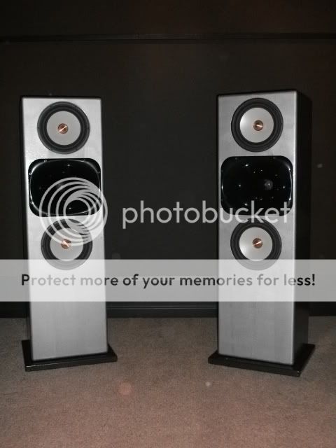
Here is a link documenting some of the work...HTGuide Forum - The Raptor ... a 10" MTM
Some of the results...
In-room system distortion sweep...
2M vertical polar response, no smoothing, on axis and +/- 15 degrees anechoic (vertically symmetric).
2M horizontal, no smoothing, on axis and +/- 30 degrees (Toole's 60 degree horizontal coverage window).
A few more pics and measurements are posted at the HTGuide link above.
Paul, you must be bored - I thought you already had the system to end the quest for all systems ;-) . Fantastic polars btw. I can only hope I come close to this.
(note to self: must complete the half finished system rebuild that I've been contemplating for two years!).
(note to self: must complete the half finished system rebuild that I've been contemplating for two years!).
Last edited:
Member
Joined 2003
- Status
- This old topic is closed. If you want to reopen this topic, contact a moderator using the "Report Post" button.
- Home
- Loudspeakers
- Multi-Way
- Large midrange for OB??? Scott G ?