Member
Joined 2003
Thanks Markus, now the next move is yours ")
Cuibono...anytime, the price of admission is only a bottle of wine!
SunRa & CLS Thanks, compliments like that make all of the splinters and nicks worthwhile. More info on the WG & phased array is at the link between pics.
tnargs, I agree AT screens are not truly transparent but the new Seymour XD material is really quite good. A couple of db EQ at the top end is necessary.
Paul
Member
Joined 2003
CLS,
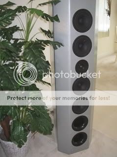
Here's how the arrays work...
-outer 8 drivers are series/parallel for 16 ohms
-inner 4 drivers are series/parallel for 8 ohms
-outer 8 and inner 4 groups are wired in series
-shunt cap across the outer 8 driver combination
-all 12 drivers share the load equally at the 70hz lower crossover
-as frequency increases toward the 800hz upper crossover, shunt diverts drive signal from outer 8 to inner 4
Here are some of the sims I used in development. Both sims use idealized drivers (flat 20-20k) to illustrate the concept.
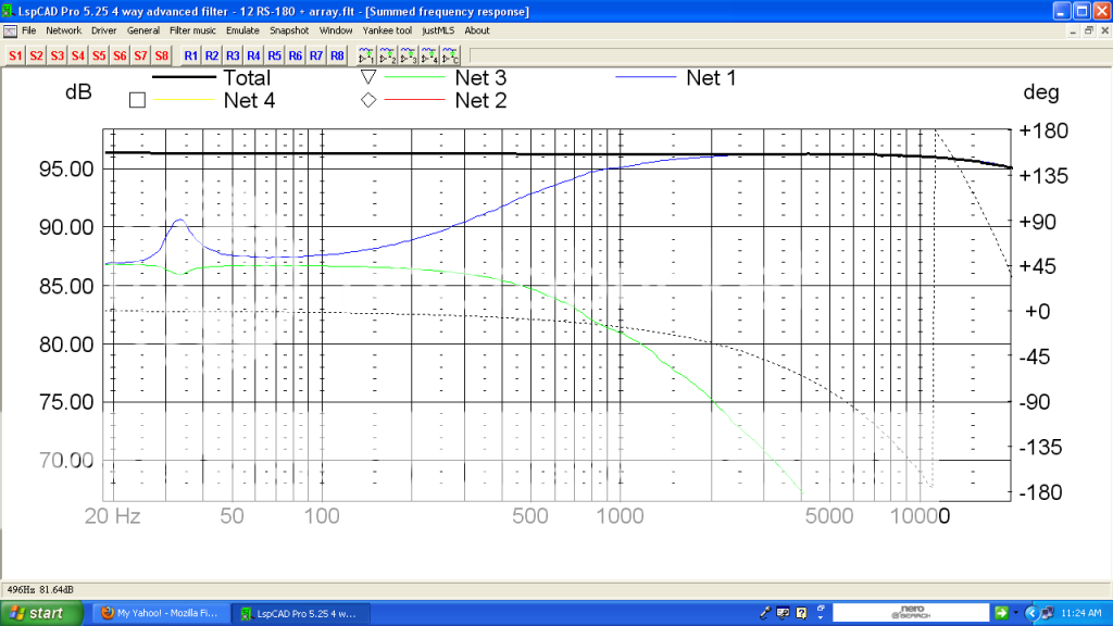
Summed frequency response on-axis:
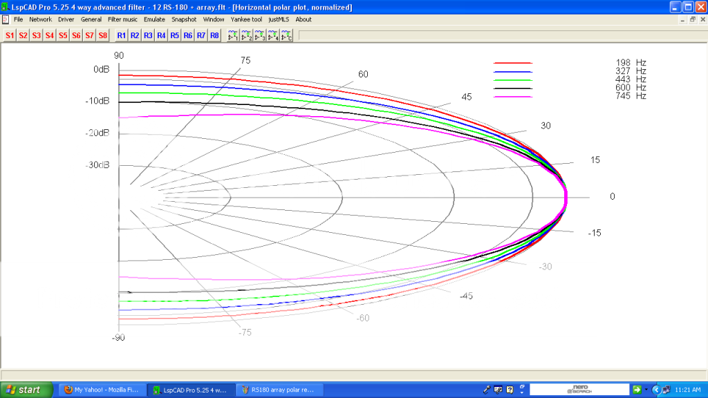
Polar response:
The shunt can be changed to many different configurations for different response.
Paul
Here's how the arrays work...
-outer 8 drivers are series/parallel for 16 ohms
-inner 4 drivers are series/parallel for 8 ohms
-outer 8 and inner 4 groups are wired in series
-shunt cap across the outer 8 driver combination
-all 12 drivers share the load equally at the 70hz lower crossover
-as frequency increases toward the 800hz upper crossover, shunt diverts drive signal from outer 8 to inner 4
Here are some of the sims I used in development. Both sims use idealized drivers (flat 20-20k) to illustrate the concept.
Summed frequency response on-axis:
An externally hosted image should be here but it was not working when we last tested it.
Polar response:
An externally hosted image should be here but it was not working when we last tested it.
The shunt can be changed to many different configurations for different response.
Paul
CLS,
Here's how the arrays work...
-outer 8 drivers are series/parallel for 16 ohms
-inner 4 drivers are series/parallel for 8 ohms
-outer 8 and inner 4 groups are wired in series
-shunt cap across the outer 8 driver combination
-all 12 drivers share the load equally at the 70hz lower crossover
-as frequency increases toward the 800hz upper crossover, shunt diverts drive signal from outer 8 to inner 4
Here are some of the sims I used in development. Both sims use idealized drivers (flat 20-20k) to illustrate the concept.
Summed frequency response on-axis:
An externally hosted image should be here but it was not working when we last tested it.
Polar response:
The shunt can be changed to many different configurations for different response.
Paul
Hi Paul - great system!
What you describe as "shunting" seems to be the same as I outlined with my "Split Power Technique" ? - with a different aim in mind !
Audio and Loudspeaker Design Guide Lines
The beauty of shunting speakers is the load balancing effect at the low end - I completely agree.
To use this technique to get radiation pattern control is something I do in the mid / low-mid department and also in the low / very low department (not in the extend of your system though) - works fine for me too.
Happy to see this somewhere else. Beautiful plots as well.
Michael
Last edited:
Member
Joined 2003
Michael,
Yes, the concept (by either name) works well. Dunno if anyone had done it before, but I first used shunts for polar management and power handling back in 2002 or 2003 when I built these speakers...
The TERMINATOR page
Paul
Yes, the concept (by either name) works well. Dunno if anyone had done it before, but I first used shunts for polar management and power handling back in 2002 or 2003 when I built these speakers...
The TERMINATOR page
Paul
I'll have to run FR and impedance charts again someday. But there wasn't much difference to the ear.
That's because there's not in a high CR compression driver. It's tiny rear chamber volume is actually almost an IB, so making it bigger won't help, only smaller which will raise its F3, Fb and what a loading cap does.
About all that removing the cap does is cause comb filtering with the horn's output since it's now a BLH with a really bad delay problem.
GM
1" Ultra Compression driver
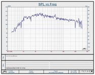
Dear all and in particular panomaniac,
I have finally managed to find my measured response for the 'home made' 1" driver with Radian diaphragm.
Please find the graph attached with my best wishes for your kind perusals.
a1greatdane
Dear all and in particular panomaniac,
I have finally managed to find my measured response for the 'home made' 1" driver with Radian diaphragm.
Please find the graph attached with my best wishes for your kind perusals.
a1greatdane
Attachments
Paul, I was just wondering, why did you choose such a big distance between the 15" drivers for your Bass Array?
I know that probably still are within the required distance dictated by the frequency, but still, wouldn't be gathering them more closely render some advantages?
Thank you!
I know that probably still are within the required distance dictated by the frequency, but still, wouldn't be gathering them more closely render some advantages?
Thank you!
Member
Joined 2003
Dear all and in particular panomaniac,
I have finally managed to find my measured response for the 'home made' 1" driver with Radian diaphragm.
Please find the graph attached with my best wishes for your kind perusals.
a1greatdane
Looks like the alteration to the phase plug worked well!
Do you still have the impulse file to "convert" to CSD?
Member
Joined 2003
Hey Scott,
Subjectively, the ND1460As "exceeded expectations". Very smooth sounding with extended response. No hint of a horn/CD sound. Quite satisfied with them.
Paul
PS: More objectively, here is in-room response at the 4 meter listening position at 0, 10, 20, 30, 40 degrees, no EQ. Short gate to deal with room reflections. 40 degree measurement is over 8 feet off-axis, so the microphone is close to the side wall of the room.
Is it me or it seems that above 10Khz the wave-guide looses directivity? I am comparing this to the graphs posted by Dr. Geddes, where the directivity seems to be maintained on a greater degree.. Maybe it has to do with the large size of the waveguide?
Otherwise, this is an excellent graph
Otherwise, this is an excellent graph
Member
Joined 2003
Directivity above 10k is likely more influenced by the driver than the waveguide.
-This is a 1.4" exit driver rather than the 1" Earl uses.
-Driver breakup is around 15k which can lead to chaotic off-axis response.
The area I would like to improve is the on-axis dip around 5k, but it seems characteristic of the symmetrical OS flare.
-This is a 1.4" exit driver rather than the 1" Earl uses.
-Driver breakup is around 15k which can lead to chaotic off-axis response.
The area I would like to improve is the on-axis dip around 5k, but it seems characteristic of the symmetrical OS flare.
Hi there,
I do know Andrea, R&D Engineer at 18Sound intently listened, when we had a little chat about the ideal sizes for software/moving assembly parts in Compression drivers at the Frankfurt Music Fair, before embarking on the 18Sound range...
You might have noticed the coil sizes on some of the 18Sound transducers differ from other's manufactures empirically established ones?
Kind regards
Sven R. Olsen aka 'Dr' O aka a1olsen aka a1greatdane
CSW-Chilli Sound Works
- Status
- This old topic is closed. If you want to reopen this topic, contact a moderator using the "Report Post" button.
- Home
- Loudspeakers
- Multi-Way
- Large midrange for OB??? Scott G ?