These spekers will be used for party's so high output will be important. Covering 140 to 6Khz with a point source seem to be a good ideea. The Seleniums are reated at 75W and they can be crossed as low as 500hz. This gives more room to play, and a wider variety of drivers.
In the future i will try to use a 2"coaxial drivers. But they are not that cheap!
Most of my most successful projects have been 'inspired' by existing designs. In the spirit of that, a couple of ideas you might try:
1) Copy the Sound Physics Labs Runt. Compression driver is BMS 4550, about $149. That's what William Cowan did, with an xover of 900hz: http://www.diyaudio.com/forums/mult...e-bandpass-mid-unity-horn-43.html#post2856266
There's enough info on the Runt online to make a successful copy. There's a thread on avsforum with pictures and measurements.
or...
2) Copy the VTC Paraline with the dual eights. The VTC Paraline *also* uses a BMS 4550, but there's a pair of them IIRC. (I'm not 100% sure on that comment; I believe some of the VTC boxes use a single compression driver on a Paraline.)
There are pluses and minuses to both approaches. The SPL Runt doesn't have directivity control as low as the VTC Paraline does. BUT the VTC Paraline is going to need DSP delay, due to the large distance between the midranges on the horn and the compression drivers. (There's something like 10" of horn length inside of the Paraline, and you need delay to compensate for that.)
If it were me, I'd probably go with the Paraline, and spend $99 on a minidsp to do the delay and xover duty. I prefer the Paraline mostly because the BMS compression driver doesn't have to work as hard on the Paraline because there are two of them. In the avsforum thread the owner of the SPL Runts complained that the high end was a bit harsh, and he'd EQ'd the top end to be down about 10-20dB to compensate. I've never found the BMS to be harsh, so my 'hunch' is that the use of an 8" midrange forced Danley to use a xover point that was lower than ideal for the compression driver. (900hz, according to Cowan.) And with such a low xover point, the compression driver is put through a lot of strain, and that strain exhibits itself as 'harshness' in the treble.
Or you could simply do what Art Welter did, and do the Paraline with large format compression drivers. You lose some top end, but the larger drivers will take a lot more abuse than the BMS 4550. In a prosound environment I doubt the audience will care if the last octave is AWOL
Danley designed the Yorkville TH sub, but not the top cabinets.1) Copy the Sound Physics Labs Runt. Compression driver is BMS 4550, about $149.
or...
2) Copy the VTC Paraline with the dual eights. The VTC Paraline *also* uses a BMS 4550, but there's a pair of them IIRC. (I'm not 100% sure on that comment; I believe some of the VTC boxes use a single compression driver on a Paraline.)
I've never found the BMS to be harsh, so my 'hunch' is that the use of an 8" midrange forced Danley to use a xover point that was lower than ideal for the compression driver.
Or you could simply do what Art Welter did, and do the Paraline with large format compression drivers. You lose some top end, but the larger drivers will take a lot more abuse than the BMS 4550. In a prosound environment I doubt the audience will care if the last octave is AWOL
The Yorkville designed PSA1 uses four 8" front loaded drivers and two 1.75" diaphragm drivers, the VTC EL210 uses two 10" drivers in an offset horn (small speaker ports) and two HF drivers.
In both designs the placement of the Paraline exit is physically a bit over 1/4 wavelength from the LF driver exits or center to center distance, so off axis response in the crossover region is not optimal.
I use 8" and EV DH1AMT 3" diaphragm drivers, which avoids the problems around the acoustic crossover point.
Other than above 15K, the DH1A has more clean output potential than the pair of BMS 4550.
For home use I would not use the Paraline, the narrow vertical dispersion it affords is not required, and the sound quality of the Paraline is not as good as the usual Synergy/Unity style horn.
Using a 3" diaphragm driver in a Synergy style horn allows a lower crossover point and the use of 8" drivers, making a 3 way system (HF, MF, separate LF) viable for high volume use.
At the levels most listen at for home use, most 1" exit drivers could be crossed over to 6" or 8" cones and still sound fine and be safe.
Art
I think you are either over thinking this or don't understand these horns.
noone says you cant be creative
we havent yet seen the optimal hifi unity
btw, tweeter is not a compression driver, but a complete small tweeter horn, and could be the new FaitalPro FD371
well, they are very creative designers, so I think we could expect more than just a cosmetic makeover
not sure Danley is even interested in that really
sounded more like he would like to see what kind of thing his crew would create
but winslow is right
either I overthink it, or have no clew
I do that with life in general
not sure Danley is even interested in that really
sounded more like he would like to see what kind of thing his crew would create
but winslow is right
either I overthink it, or have no clew
I do that with life in general
Well i think the crucial thing is to find a suitable woofer... Integrating the tweeter for PA use won't be to hard. The midrange driver will be able of 127 dB crossed at 500 hz . Sounds good.
My pockets are empty for the moment so i hope i will to use only 2 woofers/horn.
Bdw!!!
Aprox...how big is this monster? :-S in Yorkville speakers, the horns looks like an 300hz horn, and i assume that the woofers work to less than that(100hz?).
Synergy horn seems to be the best of the pack.
. Sounds good.My pockets are empty for the moment so i hope i will to use only 2 woofers/horn.
Bdw!!!
Aprox...how big is this monster? :-S in Yorkville speakers, the horns looks like an 300hz horn, and i assume that the woofers work to less than that(100hz?).
Synergy horn seems to be the best of the pack.
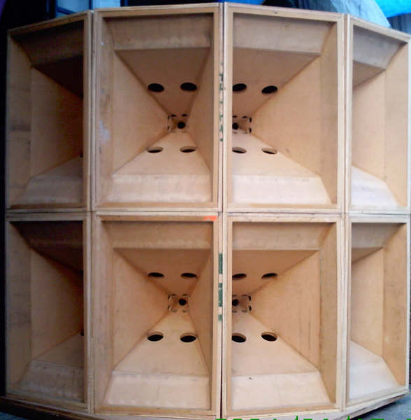
did not want to start another thread to ask this question, does anybody have a cut away view of the jericho series speakers. I am mostly curious how the many drivers are combined/mounted inside....mostly just curious.
If ths is not disclosed or public info, than please ignore my request. I am puzzled by the designs.
Steve Garrett
If ths is not disclosed or public info, than please ignore my request. I am puzzled by the designs.
Steve Garrett
did not want to start another thread to ask this question, does anybody have a cut away view of the jericho series speakers. I am mostly curious how the many drivers are combined/mounted inside....mostly just curious.
If ths is not disclosed or public info, than please ignore my request. I am puzzled by the designs.
Steve Garrett
The layered combiner in the Jericho and the Paraline in the Genesis horns work in a similar way. Basically the devices constrain the output of the compression driver into a path that's so small, the wavefront can't form.
In the Paraline the output from the compression drive is 're-assembled' into a ribbon shaped wavefront; in the layered combiner it's 're-assembled' into a square.


^^^ layered combiner ^^^
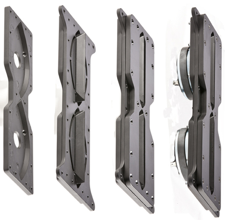
^^^ Paraline ^^^
Each device has it's upsides and downsides:
1) Unless I'm missing something, the path in the layered combiner is not optimum. The path in the Paraline, by comparison's sake, is pretty close to radial expansion. This isn't necessarily a bad thing; it appears that getting the pathlength right was more important than having the optimum expansion rate.
2) Danley's published some papers critical of line arrays; this may be the reason that the Paraline speakers are sold by VTC and Yorkville
3) There's some serious upsides to both devices. I've built a LOT of unity horns, and in my opinion, the most difficult thing to get right is getting the midrange to play above 1khz. So the layered combiner and the Paraline allow you a lot more flexibility when it comes to xover points. I have no idea what the xover point is in the Jericho horns, but I don't think it would be possible to generate these levels of output any other way. (since high frequency drivers suffer from comb filtering in such a huge way.)
Hi Patrick
Yes they are similar or at least the same rules govern the operation. It may be age creeping up on me but when I had the idea for the Paraline, that solidified in a couple days to where I could draw and build one.
I had similar initial flash of the idea and told my partner I thought a saw a way to combine multiple drivers without interference. That flash went out and turned out to be a 4 month ordeal to get a workable approach and for a while I wasn’t sure it could happen.
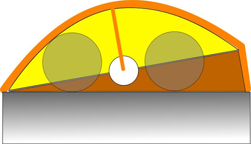
I would offer, in the figures from the patent application, the pictures are actually distorted vertical vs horizontal. For a reference, those would have been 1.4 inch BMS coax drivers in that drawing.
A 4 driver version of that one is actually easier to picture as it has full symmetry. The object of course is to have the device radiate a curved wavefront into the horn section for frequency ranges where that exit is governing the directivity (up high). Adjusting the length of the dotted line paths changes the curve.
Also, the layered combiner in the J-3 and J-4 are simpler and much smaller due to the drivers used.
I am working on a “large” speaker too since the stadium area is a place where the sound difference is a big deal.
I think you would enjoy it, a giant Synergy horn with 64 hf compression drivers, 44, 5 inch mid drivers and 16, 12 inch horn loaded woofers in a horn with a 120 inch tall by 45 inch wide mouth. I don’t think I will be having a pair in my livingroom.
Best,
Tom
Yes they are similar or at least the same rules govern the operation. It may be age creeping up on me but when I had the idea for the Paraline, that solidified in a couple days to where I could draw and build one.
I had similar initial flash of the idea and told my partner I thought a saw a way to combine multiple drivers without interference. That flash went out and turned out to be a 4 month ordeal to get a workable approach and for a while I wasn’t sure it could happen.
I would offer, in the figures from the patent application, the pictures are actually distorted vertical vs horizontal. For a reference, those would have been 1.4 inch BMS coax drivers in that drawing.
A 4 driver version of that one is actually easier to picture as it has full symmetry. The object of course is to have the device radiate a curved wavefront into the horn section for frequency ranges where that exit is governing the directivity (up high). Adjusting the length of the dotted line paths changes the curve.
Also, the layered combiner in the J-3 and J-4 are simpler and much smaller due to the drivers used.
I am working on a “large” speaker too since the stadium area is a place where the sound difference is a big deal.
I think you would enjoy it, a giant Synergy horn with 64 hf compression drivers, 44, 5 inch mid drivers and 16, 12 inch horn loaded woofers in a horn with a 120 inch tall by 45 inch wide mouth. I don’t think I will be having a pair in my livingroom.
Best,
Tom
Patrick is now probably wondering if he can get that mounted on his dashboard. ..
That would be nice to see!
Patrick is now probably wondering if he can get that mounted on his dashboard. ..
Of course!
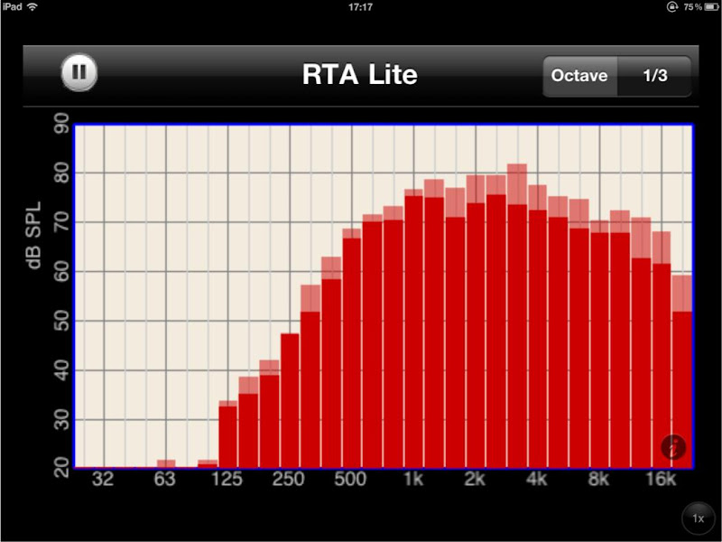
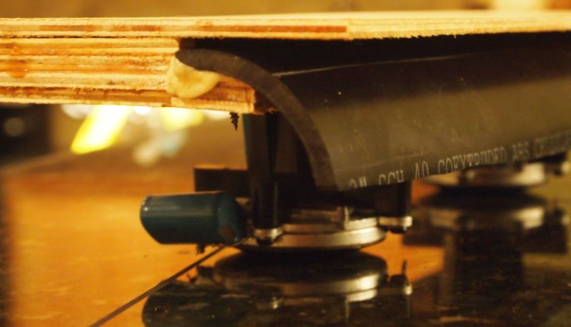
Above are some pics of the CAD plans, the frequency response, and a picture of my 'stargate' project. It's basically a Paraline cut in half.
I tried a TON of solutions which were more complex than this; some really byzantine reflectors and strange folding schemes.
But in the end, simply cutting a Paraline in half worked really quite nice!
The device has these features:
1) The unequalized response covers three octaves with a window of +/- five db. Sure, you can do better than that with a waveguide. But I can fix frequency response with an EQ. And it's still pretty good.
2) More importantly, the off-axis response 'maps' the on-axis response to a high degree
3) The super skinny mouth of the horn allows for really wide vertical response. Which is really handy when the listeners are located off-axis, like in a car
4) The device is tiny. The mouth is less than a quarter of an inch tall.
Last edited:
Hi Guys
Patrick, outstanding kluging!
That is what I like to see, actually making things and figuring out how it works.
A one sided version is just fine too, the very first one I made was one sided and my inspiration was an AT&T microwave horn.
Reflectors are frequency dependent but the correction slot isn’t so Paraline #1 had the side profile of one of these;
AT&T microwave tower, Pinckard, AL | Flickr - Photo Sharing!
Fwiw, it was made from layers of plywood also.
Anyway, nice sleuthing, the loop of building, measuring, learning, altering, building, measuring, learning is the REAL R&D.
Bill W., the fat lady hasn’t sung on “the issue”, I may know more in a couple weeks.
Best,
Tom
Here's an interesting aspect of the Paraline and the Layered Combiner which wasn't immediately obvious to me.
In our Unity and Synergy horns, we have a hard time getting the midranges to play high enough. I would argue that it's the single most difficult aspect of the design. Look at this thread - it goes back for years. Getting the midrange right is really tricky.
Wouldn't it be nice if we could simply lower the xover point on the compression driver?
For instance, instead of trying to get the midrange to go to 1500hz, what if we dropped the xover on the compression driver to 750hz? That would solve a lot of challenges, and might make it possible to do a really simple Unity horn two-way. Eliminates an xover point, reduces the number of drivers, simplifies the xover, etc.
Well, the Paraline and the Layered Combiner make it possible. Because combining compression drivers doesn't just let you raise the output of the loudspeaker. It also allows for a lower xover point.
For instance, a home loudspeaker with TWO compression drivers per side might sound like complete and total overkill.
But consider this:
1) You can get a pair of Dayton D250Ps for under $100
2) A single D250P should be crossed over around 900hz; a pair of them in a Paraline could likely go as low as 700hz, maybe even 500hz.
The reason that this works is that the Paraline loses directivity control like any horn does, so there is a point where the two drivers in the Paraline are constructively reinforcing the other drivers output.


We see that in the graphs above. In the top measurement, of a conventional horn, the CDX1-1425 is rolling off at a rate of 32db/octave. In the second measurement, of one of my Paralines, the same compression driver is rolling off at a rate of about nine db per octave.
What a difference, huh? I believe this is because the Paraline loses directivity around 1700hz, and then the two drivers begin to sum constructively.
It's a bit unique too, because you can't easily do this any other way. For instance, if you tried to do the same thing with a line of ribbon tweeters, you'll find the Paraline outperforms it because the ribbon tweeters have basically zero excursion. And if you try to do it with conventional dome tweeters, you'll get horrendous comb filtering because the tweeters don't have the right directivity.
Basically you want *narrow* directivity at high frequency, so the two drivers don't interfere with each other. And you want *wide* directivity at the low end of the drivers, so the two drivers reinforce each other's output.
Which is exactly what the Paraline gives us.
And with two drivers you dont need to push them as hard to play the same spl.
So a lower crossover point is possible because the distorsion goes down when the spl/driver goes down.
True, but it gets a little bit tricky.
You want narrow directivity on the top end, and wide directivity on the bottom end. Basically so that they *don't* interfere at high frequencies, where they'll screw each other up. But at the low end you WANT them to interfere with each other, where you need the displacement.
Just thinking out loud here, ideally you'd want a 2 x 2 matrix of tweeters that meet this criteria. By quadrupling the surface area you can go one octave lower.
Come to think of it, another interesting option might be to simply subdivide a Unity horn into four horns. For instance, instead of using a Unity horn that measures 50 degrees by 50 degrees, one might use *four* Unity horns that are each 25 degrees by 25 degrees.
I know this sounds like crazy talk, but it's really not as crazy as it sounds. Quadrupling the surface area of the compression driver lowers the xover point by an octave. About the only way to get comparable results is with something like a Tad Beryllium driver, and those cost about 10-20x as much as the Dayton, B&C and BMS drivers. (Basically the TAD attacks the problem from the other direction. My solution uses an array of small compression drivers to lower the xover point; the TAD Beryllium drivers use a large diaphragm that's extremely light to extend the response beyond what a mylar diaphragm of that size could do.)
Hmmm I might have to try this, unless someone can tell me why it's a bad idea.
Normally the use of multiple tweeters is a bad idea, but the trick is that the horns control directivity to a point where they're *not* interfering with each other.
I know that Geddes did some tests with the Tad and the B&C, and he found that the Tad sounded no better. The catch though, is that the frequency range was the same for both drivers. The real strength of the TAD is that it can cover a wider bandwidth than the B&C. (IE, what's the point of using TAD unless you need it's ultra-wide bandwidth?)
Another interesting aspect of constant directivity horns is that most of the output is at the center of the horn. So when you put two horns right next to each other, you get a relatively seamless transition from horn to horn.
Last edited:
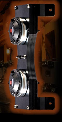
Beyma TPL-150 with compression/dome midranges
Hey Guys.
I’ve been following this threat with great interest for quite a while now and I have a couple of questions for the experienced Synergy folks.
Since I’m very fond of the Beyma TPL-150 AMT I’ve been fiddling with the idea of getting it to work in a Synergy horn. Due to the geometry of the Beyma’s faceplate I’m able to get the midrange holes very close to the throat (~2cm distance in a 60x30 horn). The area of the AMT diaphram, which is also the area at the throat is 31.25cm^2. This translates to a circumference of 19.8cm = ~1740Hz.
The area where the midrange/s tap into the horn is 67.5cm^2 = 29.1cm = ~1180Hz. This calls for a fairly low x-over point to the Beyma.
My real questions does not directly relate to the above math, so here they are:
1. Since the geometry of the Beyma faceplate allows me to place the midrange, thus the mid-holes very close to the throat, why not just use one 2” compression driver >500Hz. Are compression mid-drivers just plain no-no? (I have a pair of Community M200 + JBL 2482 on layaway)
2. Why not use a pair of large, say 3” dome midranges, is this related to dome geometry?
3. Is the Beyma a bad choice altogether, Synergy-wise?
/Thomas
- Home
- Loudspeakers
- Multi-Way
- Suitable midrange cone, for bandpass mid in Unity horn.