If you have the T/S parameters to a closed back driver, then you should NOT include a back chamber.
To wire drivers in series/parallel you just use node numbers arranged in series/parallel. In the below example the "+" terminal is node number 2 and the "-" terminal is 0. Mid drivers 2 and 3 are put in series by node number 48. Mid drivers 4 and 5 are put into series by node 49. The whole thing is in parallel because of applying drive voltage between nodes 2 and 0.
Driver 'D2' Def='MidDriver' Node=2=48=100=120
Driver 'D3' Def='MidDriver' Node=48=0=101=121
Driver 'D4' Def='MidDriver' Node=2=49=102=122
Driver 'D5' Def='MidDriver' Node=49=0=103=123
Attachments

Thanks all Akabak gurus.
Once again with Akabak, once you see an example it makes perfect sense but to think through it is a lot trickier. It would be nice if you could name the nodes more intuitive names (like PositiveTerminal instead of just 0)
I am glad that the rear chamber is not needed as this means that I am actually learning something.
I have simulated my 60x60 horn again with the Celestion TF0410MR 4" closed back midrange drivers that Paul Spencer is organising a group buy for. You can see that the -3db point is just under 300Hz which is backed up by Paul's measurements. This has been modelled for maximum output at 120db which is basically just my target for dynamic range and to keep distortion extremely low. This does come at the expense of HF linearity due to larger input ports.
To achieve 120db I have had to use 2x 2cm ports per driver which achieves just over 17m/s port velocity. You can also see that the drivers are only moving a maximum of 0.6mm which should result in very low distortion at realistic levels. To achieve 120db in a 2 Parallel x 2 Series driver configuration only 54W is needed. Who is going to listen at 120db anyway?
Interestingly you can see the same 'twin peak' predicted response that keto has measured on the previous page of this thread. I guess that DSP is the DIY easy solution to the problem.
Thanks for your help everyone.
Cheers,
Mike
Attachments

Mike,
In my room I listen at about 3m away and SPL doesn't drop a great deal from 1m. I estimate at around 5db. So I need about 110 db @1m to reach THX reference. Anything more is headroom, nice to have. So with a Synergy horn you can easily have 10 db headroom, or only slightly less in a bigger room. With S2 each driver only requires 0.1w to reach THX levels.
In my room I listen at about 3m away and SPL doesn't drop a great deal from 1m. I estimate at around 5db. So I need about 110 db @1m to reach THX reference. Anything more is headroom, nice to have. So with a Synergy horn you can easily have 10 db headroom, or only slightly less in a bigger room. With S2 each driver only requires 0.1w to reach THX levels.
Mike,
I noticed that you are using Node 1 to drive your speakers. Do understand that Node 1 in Akabak is a perfect voltage source that has zero source impedance. It would be to your advantage to include your amplifier's output impedance, and any associated speaker wire resistances in your model. Without this, the low end response of each driver type (i.e. comp driver / mid / woofer) will model as being much more damped than it really is. Once you account for this series resistance you'll see the bottom end is a bit under damped. I've always been in favor of modeling things as close as real life as I can get them.
You'll need to define the output impedance by placing the below Rg term between your midrange entry port definitions and the S areas and L lengths that define the expansion of your horn. This should be near the top of your Akabak code. The value for Rg should be whatever you output impedance plus wiring resistance. For a tube amp this would be closer to 2 ohms.
Rg=0.35; |Amplifier output impedance (ohms)
You'll also need to place the below Resistor terms just before the waveguide "wg1" construct orders near the end of your Akabak code.
Resistor 'Amplifier Rg' |Amplifier output impedance
Node=1=2
R={Rg}
Mike,
"Interestingly you can see the same 'twin peak' predicted response that keto has measured on the previous page of this thread. I guess that DSP is the DIY easy solution to the problem."
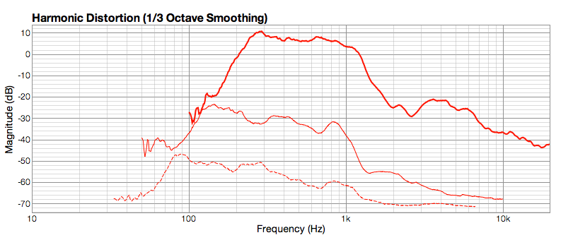
The twin peaks are less at a distance (5 meters). I'm still very new at measuring, but I've been going for the magnitude graphs that correspond to the lowest harmonic distortion. Yesterday I measured outdoors but didn't realize that the little 2W amp was distorting until I'd brought all the gear inside, so all my plots are still in-room. Also, the measurements are made with the 2-ohm load (of 4 paralleled mids) on the amp's 4-ohm tap, which may be increasing the LF hump.
I don't have a good measurement of it here, but by placing a 1st-order line-level HP @ 300hz, that lower hump pretty much disappears. I'm going for minimal filtering (done inside each pass-band's tube amp, or at line level before the amp, or at the speaker-level) and no DSP.
I find all the Akabak info you guys are talking about really interesting. I've got to figure out how to run that on my MacBook.
Is it still possible to get in on the Celestion group buy? If so, I'd take a dozen.
Thanks.
--keto
"Interestingly you can see the same 'twin peak' predicted response that keto has measured on the previous page of this thread. I guess that DSP is the DIY easy solution to the problem."
The twin peaks are less at a distance (5 meters). I'm still very new at measuring, but I've been going for the magnitude graphs that correspond to the lowest harmonic distortion. Yesterday I measured outdoors but didn't realize that the little 2W amp was distorting until I'd brought all the gear inside, so all my plots are still in-room. Also, the measurements are made with the 2-ohm load (of 4 paralleled mids) on the amp's 4-ohm tap, which may be increasing the LF hump.
I don't have a good measurement of it here, but by placing a 1st-order line-level HP @ 300hz, that lower hump pretty much disappears. I'm going for minimal filtering (done inside each pass-band's tube amp, or at line level before the amp, or at the speaker-level) and no DSP.
I find all the Akabak info you guys are talking about really interesting. I've got to figure out how to run that on my MacBook.
Is it still possible to get in on the Celestion group buy? If so, I'd take a dozen.
Thanks.
--keto
Hi everyone,
Thanks for your suggestion JLH I have incorporated that into the Synergy scripts.
The next problem that arises is the lack of T/S parameters on the BMS compression drivers' data sheets. The Synergy script has measurements for the BMS 4552ND compression driver but I have not been able to find anything for the BMS 4555. If anyone has these details (hopefully measured) are they able to post them?
For fun I had a play in LspCAD using the Behringer 2496 digital crossover filters. I have attached an image showing the output. These are only the simulated Akabak power response values and don't have any measurements so are just a theoretical approach to a Synergy horn. The transfer functions are at 300Hz and 1000Hz at 48db/octave. Potentially you could push the midrange a little bit higher (~1100-1200Hz) to help the compression driver but this is just measurement required speculation.
Cheers,
Mike
Attachments

Guys, has anyone directly compared the Misco JC5RTF-B (supplied with the original Unity) with the Pyle PDMR5 for sound quality?
The Pyle is really cheap, but just wondering if you're "paying for it" with lesser sound quality.
Thanks,
Jim
The Pyle is really cheap, but just wondering if you're "paying for it" with lesser sound quality.
Thanks,
Jim
Jim I've heard both, admittedly at different times in different horns. The original Unity kit about 3 or 4 times and my simplified version of it (S1) with the Pyle driver. The Pyle drivers are obviously cheap when you see them, but in my less than ideal comparison I didn't notice a sonic penalty in using them.
I agree with this. There is no advantage to using expensive midranges in a Unity/Synergy design. The power that the drivers see at even ear spliting levels is so low (less than 5W) that high end midranges are a waste. The featues of the more expensive midranges don't come into play at these low power levels.
JLH,
I think the Misco and Pyle are not worlds apart, both are fairly basic unimpessive drivers. The Misco is a bit better quality, with the Pyle drivers you have to be careful with the terminals, they are a little flimsy. I would be curious to hear better quality drivers compared, I'm not entirely sure the improvement would be completely lost, however I do tend to agree that the sound is strongly horn dominated. In other words, the design of the horn itself has such a big impact on the sound that differences from driver to driver, once they have been integrated properly, are going to be less than expected.
I think the Misco and Pyle are not worlds apart, both are fairly basic unimpessive drivers. The Misco is a bit better quality, with the Pyle drivers you have to be careful with the terminals, they are a little flimsy. I would be curious to hear better quality drivers compared, I'm not entirely sure the improvement would be completely lost, however I do tend to agree that the sound is strongly horn dominated. In other words, the design of the horn itself has such a big impact on the sound that differences from driver to driver, once they have been integrated properly, are going to be less than expected.
Thanks guys, I appreciate the feedback. I'm using the original Unitys with the Pyle drivers and was curious if I was "missing" anything. I think the Miscos are something like $30 a piece which is a LOT more than the Pyles.
By the way, the Unitys are mating VERY well to my Rythmik 12" servo h-frames with a 300hz crossover point. Its a great combo.
-Jim
By the way, the Unitys are mating VERY well to my Rythmik 12" servo h-frames with a 300hz crossover point. Its a great combo.
-Jim
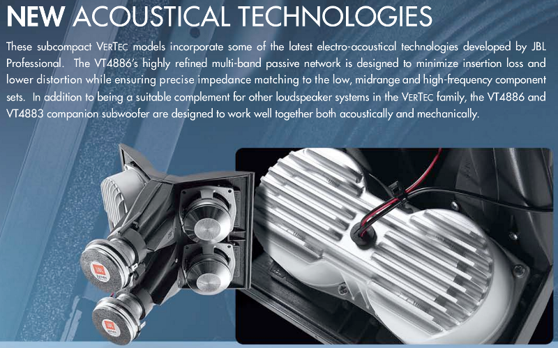
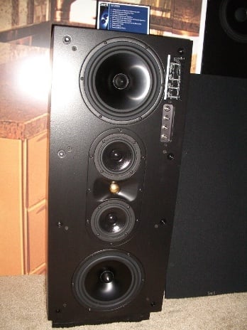
Yesterday I stumbled across the fact that the JBL Vertec arrays use some very Unity-horn-ish concepts. In particular, a coupling chamber on the midrange drivers. The patent also shows the use of foam in the coupling chamber, a la Geddes, but they've stopped doing that. The patent even references Danley's patent at Sound Physics Labs, so they were definitely, uh, "inspired" by the Unity.
Here's the back of the midrange and high frequency array. Look familiar?
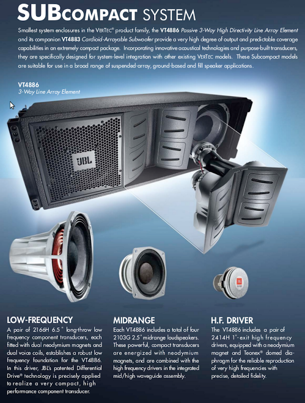
You can control directivity with a waveguide, but you can also control it with an array. In the Vertec, it's interesting that the D'Appolito arrangement controls low frequency directivity, while the waveguide at the apex does the same. It allows JBL to get the directivity of a much larger waveguide in a compact box. (This thing is tiny - not much larger than a bookshelf speaker.)
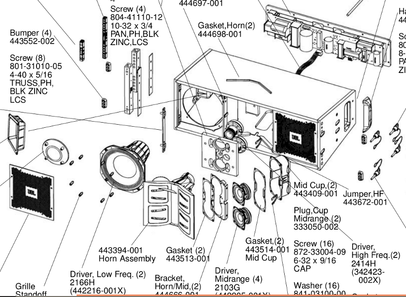
The whole array is about $3000. It's passive. Here's some part numbers, in case you want to use the JBL parts for your Unity horns. The midranges are about $100 each. Definitely pricey for a 2.5" midrange, but not all that outrageous compared to the Faital 3FE20, which has a smaller voice coil.
It's not obvious from the picture, but the woofers have a coupling chamber also. (again, very much like the Unity.) The woofer coupling chamber is formed by a metal plate behind the woofer grille, behind the JBL logo. It covers the majority of the woofer cone.
Here's the measurements. Seems like a promising design for hifi or home theater. It was heartening to see that many of the design choices I made in my small Unity horns were mirrored by JBL. (I've never seen this box until today - I came up with the idea of using 2" and 3" midranges along with small neo compression drivers without seeing this design.)
The earlier designs used a different shape for the waveguide; I'm a bit curious if the newer design is optimized to reduce interference from the compression drivers. The JBL literature notes that the waveguide and cabinet is designed to reduce diffraction, again a la Geddes.
Here's the back of the midrange and high frequency array. Look familiar?
You can control directivity with a waveguide, but you can also control it with an array. In the Vertec, it's interesting that the D'Appolito arrangement controls low frequency directivity, while the waveguide at the apex does the same. It allows JBL to get the directivity of a much larger waveguide in a compact box. (This thing is tiny - not much larger than a bookshelf speaker.)
The whole array is about $3000. It's passive. Here's some part numbers, in case you want to use the JBL parts for your Unity horns. The midranges are about $100 each. Definitely pricey for a 2.5" midrange, but not all that outrageous compared to the Faital 3FE20, which has a smaller voice coil.
It's not obvious from the picture, but the woofers have a coupling chamber also. (again, very much like the Unity.) The woofer coupling chamber is formed by a metal plate behind the woofer grille, behind the JBL logo. It covers the majority of the woofer cone.
Here's the measurements. Seems like a promising design for hifi or home theater. It was heartening to see that many of the design choices I made in my small Unity horns were mirrored by JBL. (I've never seen this box until today - I came up with the idea of using 2" and 3" midranges along with small neo compression drivers without seeing this design.)
The earlier designs used a different shape for the waveguide; I'm a bit curious if the newer design is optimized to reduce interference from the compression drivers. The JBL literature notes that the waveguide and cabinet is designed to reduce diffraction, again a la Geddes.
Last edited:
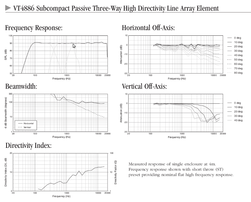
Though the VT4886 has much better horizontal dispersion characteristics than the small format VLA series, it shares it’s design with the VT4889, 4888 and 4887, the VT 4886 is simply a shrunken version of the above marketed towards those that believe a line array is the solution to all audio needs.
The entire VT line is simply JBL’s answer to the L-Acoustics' V-DOSC line array from the early 1990s, they are nearly identical in design concept (using diffraction for HF dispersion) , not very similar to the Synergy horn design concepts.
JBL’s Precision Directivity series, and Renkus Heinz Co entrant horns are far more similar in concept to the Synergy/Unity horn than the VT series.
Because the VT886 is so small (only 22.8” wide), the wavelengths at the crossover points are almost (close but no cigar) short enough to constructively combine, so it has better midrange dispersion characteristics than its larger brethren.
Better is not that great, or very close to the even dispersion a Synergy style horn can afford, as is evident in the comparison of the VT 4886 horizontal dispersion to the VTC eL210 which uses a Paraline HF coupler and Synergy style mid porting on a straight sided (semi conical)horn.
The VTC eL210 has a uniform - 6dB 90 degree horizontal coverage pattern from below 500 Hz to 20K, the VT886 at 90 degree level varies about +1 dB to -7dB over the same range.
Art Welter
Attachments

Last edited:
An externally hosted image should be here but it was not working when we last tested it.
Here's a pic of the Precision Directivity design. The PD764 is like a 'horn within a horn'. I'd argue the Unity and Synergy designs are like a 'horn stacked on top of a horn.' And the secret sauce is manipulating the dimensions so that the apparent source is FORWARD of the actual loudspeaker diaphragm. For instance, the diaphragm of the compression driver in a Unity horn is producing 2000hz, but that wave cannot expand until it reaches a point in the horn that's a few inches forward of the diaphragm. That's the key, and it's responsible for the excellent phase response. The PD764 doesn't have that going for it.
IMHO, the Unity and Synergy are an evolution of the D'Appolito array.

Basically fold the second speaker around a conical horn, add coupling chambers to increase efficiency and reduce distortion, and *voila*, you're pretty close to a Unity horn.
The problem with a conical horn is it's size - they're humongous. And the size is dependent on the wall angle. IE, a 135 degree conical horn is much MUCH smaller than a 45 degree conical horn. So I think JBL has (cleverly) used varying coverage angles in their array. JBL's solution maintain's a beamwidth of 90 degrees using a waveguide that's less than sixty four square inches, then trades off to a midbass array (which also controls directivity, jut not as well as the WG.)
By manipulating the dimensions of the high frequency portion of the waveguide, they can also make the compression driver's acoustic center move forward, even though the driver itself is significantly far back from the midranges.
Now if only I could find a phase response plot I could test out this theory...
I find it interesting that JBL is using four 2.5" mids in that speaker. I kind of feel like it validates my choice of using 3" cone tweeters.
Scratches head at how to do those in my car...
Sure I could figure something out that could work.
Where did I see a Unity/Synergy horn that had the backwave of the midrange ported into the horn for lowend reinforcement? Wonder if I could do that with a pair of 3s or something to get them to play down to 50o in the car door?
Sure I could figure something out that could work.
Where did I see a Unity/Synergy horn that had the backwave of the midrange ported into the horn for lowend reinforcement? Wonder if I could do that with a pair of 3s or something to get them to play down to 50o in the car door?
The thing with JBL is they will sell you any parts over the counter to say, but the speakers have to be bought from an authorized JBL Pro Parts dealer.
Just in case someone is looking to buy those little speakers.
Just in case someone is looking to buy those little speakers.
- Home
- Loudspeakers
- Multi-Way
- Suitable midrange cone, for bandpass mid in Unity horn