Measurements or Finishes?
Hello All,
Been quite some time since I have seen any activity on the thread. I am still loving my Fat Thors!
Did anybody ever get around to measuring the Fat Thor's response?
I am looking for finishing suggestions. How have others finished theirs?
Any pics/links to ideas would be much appreciated.
Thanks!
Rep
Just one question .. does the fat thor effect the overall sound or just the lowest notes?
I have experimentet alot with the XO found myself forced to tweak it again due to amp upgrade .. changed from Cheap yamaha to expensive yamaha oldtimer DSPAX1 .
It seems like the tweeter overall has to go down a tad.
I have experimentet alot with the XO found myself forced to tweak it again due to amp upgrade .. changed from Cheap yamaha to expensive yamaha oldtimer DSPAX1 .
It seems like the tweeter overall has to go down a tad.
The "fat" Thor cabs did change the over all sound some what....
The snap and speed of the mid-bass changed also.
The drivers seemed to integrate better and the mechanical devices as a whole took another step out of the way to let the musical through.
Now how much of that was the size of the box or if it was the different thickness of the panels or the reduced stuffing per cubic foot is anyone’s guess.
But I can tell you for sure that the sound went from a "good but I wouldn't buy" to an "I could easily live with these"....
Now Repute deviated from the norm in having an added compartment on the bottom for the x-overs AND some kick *** stands that look good and are solid.
I wish he would post a few pics...
Every small detail in improvement is really audible on these speakers what ever you do you will here it , maybe I´ll try the fat thor some day when I get tired of these speakers.. I have my XO outside the cabinett in a separate box really handy when improvements are to be done I can really recommend it.
jackinnj said:ever since the parts came in from Madisound it's been too cold to use the garage workshop here in NJ == I expect to cut in April.
You aren't slowing me down... haven't had much chance to massage the words much... (i do have a start thou -- althou everytime i turn around, Scott is generating more...)
dave
Got an idea.
Thor effectively is an over-complicated way of creating an aperiodic box. So let's just come up with an aperiodic enclosure and have done with it. I've been quite interested in aperiodic boxes for a few months, as they seem to offer quite a few advantages, particularly with respect to reducing the impedance at box resonance, which can only be a good thing, but there appears to be a paucity of literature on the subject, bar an excellent Ted Jordan article from 50 years ago (thanks again Dave). However, Scan Speak make some nice-looking aperiodic vents, which, according to the information on the Madisound site, 'makes your sealed driver behave as if it's in an enclosure 20% larger.' Fair enough, and I see no reason to disbelieve that statement. No much to go on, but the Parts Express site is a little more illuminating: apparently you need 1 vent per enclosure for boxes up to 1.75ft^3, 2 vents for a larger box, up to 2.75ft^3 etc. Sounds sensible enough to me. They also suggest that only 60% of the box should be stuffed, and 'a clear pathway from the rear of the driver to the vent is needed'
That last bit might be tricky, given that 60% of the enclosure should be stuffed according to the information, but if we follow the MLTL approach, the point of maximum velocity occurs at the terminus of the line, so if we stuff the upper 60% of the enclosure, leave the bottom part unstuffed, and mount the vent close to the base, by my reckoning, that should work well enough.
Assuming the above assumptions are correct, I've tried to model an aperiodic box in Martin's latest Closed Box sheet. 42" tall, 7.5" wide, 11.75" deep (internal, assuming 3/4" material). These are basically the original enclosure dimensions, albeit without the internal baffle of course. Stuff 0.35lbs ft^3 from the top 25.25" down. Each enclosure will need 2 Scan Speak 29001 'Flow resistance vents' mounted, one above the other, on the rear panel. Centre of the first should be 5 1/2" up from the internal bottom, the second 11" up (basically, as close as possible to each other, and as close to the base of the enclosure as possible). Assuming that the available information is accurate, the anechoic response should look like the attached graph, and I can’t honestly see any reason why it shouldn’t work, and work pretty well at that. Aperiodic Thor anyone?
Cheers
Scott
Thor effectively is an over-complicated way of creating an aperiodic box. So let's just come up with an aperiodic enclosure and have done with it. I've been quite interested in aperiodic boxes for a few months, as they seem to offer quite a few advantages, particularly with respect to reducing the impedance at box resonance, which can only be a good thing, but there appears to be a paucity of literature on the subject, bar an excellent Ted Jordan article from 50 years ago (thanks again Dave). However, Scan Speak make some nice-looking aperiodic vents, which, according to the information on the Madisound site, 'makes your sealed driver behave as if it's in an enclosure 20% larger.' Fair enough, and I see no reason to disbelieve that statement. No much to go on, but the Parts Express site is a little more illuminating: apparently you need 1 vent per enclosure for boxes up to 1.75ft^3, 2 vents for a larger box, up to 2.75ft^3 etc. Sounds sensible enough to me. They also suggest that only 60% of the box should be stuffed, and 'a clear pathway from the rear of the driver to the vent is needed'
That last bit might be tricky, given that 60% of the enclosure should be stuffed according to the information, but if we follow the MLTL approach, the point of maximum velocity occurs at the terminus of the line, so if we stuff the upper 60% of the enclosure, leave the bottom part unstuffed, and mount the vent
Assuming the above assumptions are correct, I've tried to model an aperiodic box in Martin's latest Closed Box sheet. 42" tall, 7.5" wide, 11.75" deep (internal, assuming 3/4" material). These are basically the original enclosure dimensions, albeit without the internal baffle of course. Stuff 0.35lbs ft^3 from the top 25.25" down. Each enclosure will need 2 Scan Speak 29001 'Flow resistance vents' mounted, one above the other, on the rear panel. Centre of the first should be 5 1/2" up from the internal bottom, the second 11" up (basically, as close as possible to each other, and as close to the base of the enclosure as possible). Assuming that the available information is accurate, the anechoic response should look like the attached graph, and I can’t honestly see any reason why it shouldn’t work, and work pretty well at that. Aperiodic Thor anyone?
Cheers
Scott
Attachments
Scottmoose said:They also suggest that only 60% of the box should be stuffed, and 'a clear pathway from the rear of the driver to the vent is needed'
The PEARL PR-2 is probably one of the most advanced aperiodic boxes that ever hit th emarket. You can clearly see this concept in the cutaway drawing.
dave
Attachments
And Bill's choice of vent. He uses acoustic foam for all his damping. I've tried this and it works, but i find that the slot port ala Dynaco is easier to tune in a 1-off situation.
The ScanSpeak vents seem a compromise to me with no tunability (and they cost $$$).
Scott -- using the sections model, set the "last" 2 sections to a 1/2" wide slot, x units long followed by a 1" slot the same length stuffed to max density (1 lb/ft^3). length of each section is 3/8". I don't know if this will work. Martin suggests just playing with a last section that is stuffed to max density ignoring any relation to what the slot ends up being in reality.
dave
Attachments
planet10 said:
The PEARL PR-2 is probably one of the most advanced aperiodic boxes that ever hit th emarket. You can clearly see this concept in the cutaway drawing.
dave
What's with the half a Turantula in the middle of the driver?
Is this a JOKE? The spider is on the WRONG side of the cone.

http://www.diyaudio.com/forums/attachment.php?s=&postid=878451&stamp=1143398144
jackinnj said:my KEF 104ab's use a B139 sans motor for, I guess, the same effect.
No. The B139 passive radiator substitutes for a HUGE port so is classified as a BR. There is an extra resonance caused by the suspension of the PR and it is important that this is low in frequency.
dave
rcavictim said:What's with the half a Turantula in the middle of the driver?
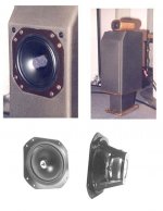
That is an artifact of a shiny cone, conversion to gray-scale, printed & scanned. Here is a color pic that might clear things up.
The 2nd order XO on these is at 1.2 kHz, the phase plug is a wool-felt cylinder. A bolt goes thru the pole-piece and attaches the woofer to a brace in the cabinet.
dave
Attachments
Cheers for that Dave. Useful. I was just idly playing around while fixing another PC really & the SS vents kick-started me a bit (I wonder if they'd been reading that TJ article you sent me?). Not cheap for what they are either. I'll give Martin's suggestion a whirl when I get chance -I reckon aperiodic should have a bit more coverage than it has at present; it's got some real potential there. Even as is, interesting to reflect that the sealed box / aperiodic box has a near as identical response to the TL original.
Cheers
Scott
Cheers
Scott
Thor Design Comments
I commented some time ago on another forum about the questionable low end extension of the Thor based on both sets of published measurements. I also did some preliminary simulations and was unable to duplicate the author's response around the crossover point. Other's also independently reported similar results and at the moment I don't remember the exact discrepancy:
http://www.diyaudio.com/forums/showthread.php?threadid=41123
My best read of the situation, given that no comments were offered by the author, Madisound, or SEAS, was that the crossover was "adjusted" after the measurements were taken, but I cannot be sure. Anyway, I found this thread interesting having looked closely at the design.
I also noted how the author shorted one driver while measuring the other and wondered how he thought that would lead to any meaningful measurement. The shorted driver acts as a low Q passive radiator. It is not really blocked, just heavily damped. In any case, as has been noted, I would not expect the measurements to be accurate.
Pete B.
Feyz said:This is how Joe D describes he did nearfield driver measurements:
"In practice, the near-field response of each woofer is measured
separately with the other woofer shorted, and then both responses are added to get the total low-frequency response
of the woofer pair."
My understanding is he measures the nearfield of each woofer driver separetely while blocking the other woofer by short circuiting its terminals, then adds the two together. I don't know much about TL's, but wouldn't this cause error? By not driving the other driver, the effective volume behind the driver being driven will be doubled from what it is in real usage, wouldn't it?
Another reason for measured differences
Several have mentioned the differences between the author's near field measurements and those taken in the SEAS anechoic chamber. It must be kept in mind that near field measurements, essentially measure volume velocity and a frequency independent scale factor is used to obtain the equivalent, usually, 1m or 2m response, into half space. A baffle step correction must be applied to obtain an accurate representation of the full space or full anechoic response. I doubt that the author applied baffle step correction to his measurement and therefore his would be a half space measurement as compared to the SEAS full space measurement.
I posted this on another forum:
"The near field measurement method was published by Don Keele in the AES and he graciously gives credit to Raymond J. Newman of Electro-Voice "for first making the observation that nearfield measurements correlated well with anechoic measurements.":
"Low-Frequency Loudspeaker Assessment by Nearfield Sound-Pressure Measurement" D. B. Keele JR.
He covers the theory and gives experimental data. In fact his figure 10 a. anechoic, shows baffle diffraction loss as compared to the nearfield measurement b. in support of my theory for why there is peaking in the nearfield response of baffle step compensated systems. His figure 10 also shows good agreement with half space far field measurements as I also stated."
Keele's papers:
http://www.dbkeele.com/papers.htm
It seems to me that the author decided not to give the design full baffle step compensation, probably to avoid excessive loss in sensitivity. This can be seen by the fact that the SEAS measured (anechoic) response droops by about 3 dB from 1 kHz down to 100 Hz. Then again, now looking I notice that the nearfield measurement of the woofer offered here:
http://www.diyaudio.com/forums/attachment.php?postid=734575&stamp=1128075761&
Shows a full 6 dB of baffle step and therefore something does not seem right. What the total anechoic measurement suggests is that the port is subtracting from the total system output around 100 Hz, and this is a problem with TLs, the port output is out of phase with the woofers over certain frequency bands. I believe that this is the reason for the droop around 100 Hz. I also believe that the author over stuffed the line which reduces deep bass output. I've mentioned this on other forums.
I derived a full T&S model for transmission line loudspeakers as a college level study many years ago and my advisor was quick to point out how l/4 resonators were a basic element in microwave design. Microwave engineers sometimes use a lumped approximation to l/4 resonators which in acoustics would be a vented system. I believe that the benchmark for the Thor should be the same drivers in an approximate B4 or B6 alignment. The author's reduction of box volume is similar to the volume reduction in going to a B6 where 6 dB of electrical boost is used to maintain the same -3dB point as the B4 in half the box volume. Original Thor's might be helped by a line level boost filter, might even want to add a few dB more of baffle step compensation.
My first designs were mostly TLs and after doing the project I decided to try to get that powerful, tight, well controlled bass from vented systems. I build vented systems with more damping than is typically used and believe that it offers the best of both worlds. I do not use material in the port as with so called aperiodic systems as I believe they are inferior to most others.
Pete B.
TL port subtraction
If we look again here at the woofer output in blue, and the total system output in black, it is helpful to visually shift the blue curve up so that they are aligned at about 150 Hz:
http://www.diyaudio.com/forums/attachment.php?postid=734575&stamp=1128075761&
Then, where the black line falls below the blue, the port is subtracting, and above the port is augmenting. Notice the dip at 25 Hz, and again at 50 Hz in the black curve which would fall below the blue curve, here the port is out of phase with the woofer output. Indeed, it looks as if the port never offers an increase in total system output. Further, there is no deep notch or dip in the woofer output as would be expected at the l/4 frequency, which should be filled in by the port output. The input impedance also suggests that the system is over stuffed and acting as a leaky box. It seems that there is so much damping that the port offers little if any reinforcement.
Pete B.
Scottmoose said:
snip
People often confuse the shape of a cabinet with what it does. The name 'Transmission Line' is actually inaccurate -it's an electrical term, not an acoustic one at all. The proper moniker should be 'Quarter-Wave Resonator' -that's what the cabinet of what we generally call a 'Transmission line' does: it is designed to resonate strongly (using the quarter-waves -now there's a surprise!) at a particular frequency set by the designer, and there are a number of ways to achieve this.
snip
Best
Scott
I'm going to have to disagree here and in fact I find this new name "Quarter-Wave Resonator" to be misleading. I actually referred to TL speakers as acoustical transmission lines (ATL) many years ago. It is true that in a resonant TL we use the l/4 resonance to augment the low end response and reduce cone excursion much in the same way as a vented system at Fb. However, TL speakers also resonate at odd and even multiples of l/4 and therefore this name tends to downplay the more problematic resonances in a TL speaker. TL speakers usually use a mismatch terminated length of acoustic transmission line as a l/4 resonator and therefore I believe the traditional name is just fine.
We will probably have to agree to disagree.
Pete B.
- Home
- Loudspeakers
- Multi-Way
- Clarity on Seas Thor Kit