The Fat Thor with a downward firing port should rock the foundations. In MathCad, the response appears to droop a little -that's delibarate because the current version of the software doesn't account for the massive boost from the floor and vertical room-mode. One tweak however -go for a 4" x 4" port rather than the 3" x 4" one I originally suggested -I've been re-working it a little, trying to get the speaker to roll off (ha!) in lock-step with room-gain. Smooths things a little. If anyone finds they want a little more lower end (possible I suppose ;-) try using a higher resistance wire -Van Den Hul carbon if you want 'audiophile' stuff, 18AWG magnet wire or the ilk should do just fine.
I've re-checked Short Thor too, just to be sure, as my original calculations were a little rough around the edges: this is the response of the cabinet as drawn by Dave (great stuff!). Doesn't go quite as low as Fat Thor, which will embarass some subs I can think of, but low enough, and it's somewhat smoother / more refined. More 'hifi' I suppose. Your choice!
Best
Scott
Attachments
jackinnj said:I may be able to have the cabinets CNC routed and laminated -- would certainly be too heavy to ship to South Africa or Europe but U.S., Mexico and Canada might work.
Well Madisound charges ~$600 and if I were to make another pair for Repute I'd charge him $1,000,000!.
To get a set CNC milled and laminated for a reasonable price would be well worth it!
"If anyone finds they want a little more lower end (possible I suppose ;-) try using a higher resistance wire -Van Den Hul carbon if you want 'audiophile' stuff, 18AWG magnet wire or the ilk should do just fine. "
So exactly what will adding a little resistance to the lowpass do? Smooth the response, extend the lowend cut off, steepen the rolloff?
Forget I mentioned the 4" x 4" port for the Fat Thor -mere blithering (I made a typo when entering the parameters and didn't notice -humble apologies. The original 3" wide x 4" long port still stands as probable optimum for this configuration)
Higher resistance wire = ye olde trick pulled by us full-range driver types. Raises the Qes a little, just enough to pull the bottom end into line -if you have a shallow rising response, or a gradual roll-off, it usually flattens it out. For example, I use 24 AWG magnet wire with a pair of Fostex FF165K drivers in one of my completed projects -a very large TQWT. Those cabinets will have a pair of FE166ES-Rs in them next weekend -with those, I'll probably shift even further to using 30AWG. Frankly, the difference will be marginal with the Fat Thor, as they don't start rolling off until below 40Hz anyway, so don't pay too much attention to it. Just a throw-away remark, so to speak. Something to experiment with in future if you feel so inclined, and a -8db point of 20Hz isn't quite good enough any more ;-)
By the way, you can chop the port of Short Thor down a little to 4". Makes the roll-off a little more uneven, but the general response is even flatter over 100Hz (you'll need to add 6db overall for the paralleled drivers to this graph -it doesn't take that into account like the one above)
Attachments
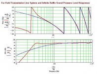
Final tweaks before I bow out. If you find the response of Fat Thor too droopy (though the floor-mounted port should utterly eliminate that -I deliberately kept the anechoic droop because of this) then increase the area of Sm to 1.75Sd, decrease the length of the vent to 2" and increase its diameter to 5". Props it up a bit more, but retains a bit of a decrease to take the port position into account.
Short Thor is my favourite though. I wanted to tweak it fractionally: all it needed was another vent mod. 4" wide, 4" long. Best response from these drivers. F3 33Hz, one of the flattest responses I've ever seen from anything. It hardly needs any stuffing at all -at a pinch, you could do without completely. 0.5Lbs ft^3 is more than enough
Regards to all & good luck with your various Thors
Scott
Scottmoose said:Final tweaks before I bow out.
Yah right we believe you. Just as soon as my material has been cut you'll come up with some new brainwave
") LOL
LOLThx for all the sims Scott. It looked pretty complicated to use MK's sheets. Is there a dumb users guide to using them? A sort of practical tutorial? If not - maybe there is a gap that needs filling, nudge - nudge wink wink.
With Thanksgiving, and getting over a nasty cold I have not done any stuffing adjustments.
The original design called for the following:
"400 g (14 oz) of the damping material should be placed in the front channel; 250 g (9 oz) in the rear."
If I recall correctly, Scottmoose indicated the Fat Thor would use the same? Please correct me if I am mistaken.
Thanks!
Rep
The original design called for the following:
"400 g (14 oz) of the damping material should be placed in the front channel; 250 g (9 oz) in the rear."
If I recall correctly, Scottmoose indicated the Fat Thor would use the same? Please correct me if I am mistaken.
Thanks!
Rep
You're welcome guys. Stuffing etc is worth playing with -stuff to taste for the room you're in is probably the way forward. As Fat Thor stands (stood?) the original quantity is what I'd start with, and adjust from there.
Martin's sheets aren't actually very difficult to use, once you get the hang of it -remember, he's done all the hard work -it's just the driver parameters and enclosure details you have to input yourself. What is trickier I suppose is knowing what to put into them in the first place, what the room will do etc. I get things wrong too! Frequently.
All right: to those who ask, shall recieve. Gentlemen, I present, for your listening pleasure, the Small Thor (everything is relative you understand ;-) Straight, Mass Loaded Transmission Line.
48" line length.
So= 2Sd
Sm=2Sd
Tweeter centre: 36" from the base (so 12" from the top)
Port = 3" diameter x 4" long. 4" from the base. Can be front or rear mounted.
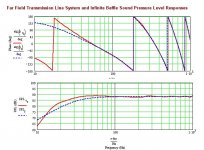
F3=39Hz. See response plot below. I like. In fact, frankly, I think these drivers work best in a straight, un-tapered line, mass-loaded. How I didn't hit on this combination before I don't know, because it works very well indeed, according to the sim, and I long ago learned to trust Martin's sheets.
Un-braced, these dimensions should give a relatively compact enclosure (yes, really!) with external dimensions of 49 1/2" x 9" x 12" (HxWxD). Just show the Significant Other the size of the others if she complains! It doesn't go as low as the Big Short Thor with a 4" x 4" port, but it's just as flat.
Onward and Upward
Scott
Martin's sheets aren't actually very difficult to use, once you get the hang of it -remember, he's done all the hard work -it's just the driver parameters and enclosure details you have to input yourself. What is trickier I suppose is knowing what to put into them in the first place, what the room will do etc. I get things wrong too! Frequently.
All right: to those who ask, shall recieve. Gentlemen, I present, for your listening pleasure, the Small Thor (everything is relative you understand ;-) Straight, Mass Loaded Transmission Line.
48" line length.
So= 2Sd
Sm=2Sd
Tweeter centre: 36" from the base (so 12" from the top)
Port = 3" diameter x 4" long. 4" from the base. Can be front or rear mounted.
F3=39Hz. See response plot below. I like. In fact, frankly, I think these drivers work best in a straight, un-tapered line, mass-loaded. How I didn't hit on this combination before I don't know, because it works very well indeed, according to the sim, and I long ago learned to trust Martin's sheets.
Un-braced, these dimensions should give a relatively compact enclosure (yes, really!) with external dimensions of 49 1/2" x 9" x 12" (HxWxD). Just show the Significant Other the size of the others if she complains! It doesn't go as low as the Big Short Thor with a 4" x 4" port, but it's just as flat.
Onward and Upward
Scott
Attachments

Guys,
I'm getting the ok from the wife to go ahead and sell the swan Divas and go for the Fat Thors... 
quick couple of questions:
1. with the down-firing port configuration, I'm a little confused on the way the pedestal is constructed to allow the air flow of the 4" port....anyone has a drawing or pic?
2. Nobody mentioned using a flared port....I'm thinking of using one to smooth out the low frequency. Any reason why not to do this?
3. I know the simulations show a better response of having he main brace from the floor up at +100deg, unlike the original thor which had the brace from the top down angled at -100deg. I'm thinking of trying the fat thor but with the brace at the original thor position (from top down, at -100 deg) with the port firing backwards from the back.....again, any reason why not to do this?
This is exciting!!!!!
I'm getting the ok from the wife to go ahead and sell the swan Divas and go for the Fat Thors...
quick couple of questions:
1. with the down-firing port configuration, I'm a little confused on the way the pedestal is constructed to allow the air flow of the 4" port....anyone has a drawing or pic?
2. Nobody mentioned using a flared port....I'm thinking of using one to smooth out the low frequency. Any reason why not to do this?
3. I know the simulations show a better response of having he main brace from the floor up at +100deg, unlike the original thor which had the brace from the top down angled at -100deg. I'm thinking of trying the fat thor but with the brace at the original thor position (from top down, at -100 deg) with the port firing backwards from the back.....again, any reason why not to do this?
This is exciting!!!!!
ssabripo said:1. with the down-firing port configuration, I'm a little confused on the way the pedestal is constructed to allow the air flow of the 4" port....anyone has a drawing or pic?
3 (or 4) legs (here copper pipe attached to a garry oak base....
An externally hosted image should be here but it was not working when we last tested it.
2. Nobody mentioned using a flared port....I'm thinking of using one to smooth out the low frequency. Any reason why not to do this?
You just have to adjust the port length to maintain the same tuning -- a flared port needs to be longer.
3. I know the simulations show a better response of having he main brace from the floor up at +100deg, unlike the original thor which had the brace from the top down angled at -100deg. I'm thinking of trying the fat thor but with the brace at the original thor position (from top down, at -100 deg) with the port firing backwards from the back.....again, any reason why not to do this?
The driver position in the pipe is important. If you flip the divider, you also have to flip the drivers as well... now they are way to close to the floor.
dave
Scottmoose said:Just show the Significant Other the size of the others if she complains!
Wasn't that a line in a Mel Brooks movie? (it certainly should have been! )
planet10 said:
......
The driver position in the pipe is important. If you flip the divider, you also have to flip the drivers as well... now they are way to close to the floor.
dave
dave...I'm confused. The original thor had the port on top with the brace coming top bottom:
An externally hosted image should be here but it was not working when we last tested it.
the "fat thor" basically uses the same X-over design, and is deeper to give it better bass reproduction, is it not? did I miss something??
so why would fliping the brace back to the original thor design require the drivers to be flipped closer to the floor? the original thor (and variations thereof) still have them in normal position.
I'm kinda confused I guess

The only reason not to do it is that the new FAT THOR has been modeled using Martin King's Worksheets. If you change the enclosure in the way you propose it is unlikely that you will get the frequency responses as predicted in the worksheets.
If you take a look at the renders that were done a little while back as well as the pair that were constructed an easy way to create a "pedistal" is to simply extend the sides of the enclosure past the usual bottom of the cabinet. If you like you can then attach another bottom plate as it is in the render - might make it a bit more sturdy.
If you take a look at the renders that were done a little while back as well as the pair that were constructed an easy way to create a "pedistal" is to simply extend the sides of the enclosure past the usual bottom of the cabinet. If you like you can then attach another bottom plate as it is in the render - might make it a bit more sturdy.
ssabripo said:the "fat thor" basically uses the same X-over design, and is deeper to give it better bass reproduction, is it not? did I miss something??
Fat Thor also has a more optmimum driver offset in the line (the original's offset was more a side effect than a design choice). The offset helps kill the 1st unwanted line harmonic, allowing either better bass (less stuffing) or better ripple (same stuffing) than the same line with the drivers pushed up as close to the end of the line as possible.
dave
Ssabripo -I'd suggest you also look at the Short Thor MLTL if you want a HUGE enclosure. It doesn't have quite as much bass as the floor-venting Fat Thor, but very close (within a couple of Hz) and its response is smoother. I recently re-visted the Thor in all it's varieties in a separate thread as I wanted to refine some of the models of Thor enclosures that I'd made before, which were a bit rough and ready, and also try a couple of other things too that I hadn't looked at before. http://www.diyaudio.com/forums/showthread.php?s=&threadid=70862
Best
Scott
Best
Scott
- Home
- Loudspeakers
- Multi-Way
- Clarity on Seas Thor Kit