Hi Niklas.
I'm supposing you might be busy doing your shift work.
Anyways, when you can, please make a measurement of one of your speakers ( in their present listening location ) using its current network .
Use the same measurement criteria as you've just used;
ie; locate the test mic, 1 meter away ( pointing at the speaker ), straight on-axis to the tweeter
This measurement should help corroborate the Z distance ( OffSet ) that I currently have arrived at.
Make this a new ( single sweep ) REW file and email it to me please ( when you are able ).
Thanks
PS; I'm offline from the 13th till late the 18th.
Yes indeed I'm busy this week but I'll try to get a measurement done tonight.
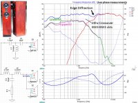
While it's on my mind, I was looking at the Group Delay traces from the files you set me and one item stood out.
See this ;
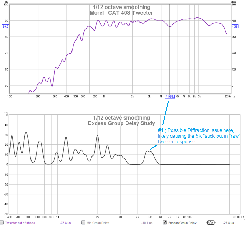
This drawing shows a possible correlation between the 5K response suck-out and some excess group delay.
I'm thinking its a diffraction artifact ( either caused by the sharp edges of your cabinet ) or a reflection coming back from the nearby woofer frames .
Either way ( if it concerns you & you want to pursue a remedy at some point ) read-up on ( Google ) about using felt treatments around the tweeter to mitigate the effect .
A really good place to start is David Ralphs Speaker Pages
Specifically ; Read his articles on ameliorating the effects of diffraction by using felt near the tweeter.
")
Interesting! Well, since I don't have any cloth grills or anything covering the front of the speaker I think I'll go with the more aesthetic option (not using felt). But hey, it could be a fun experiment if I find myself having plenty of spare time some day.


Can you post the above graph with the "invert" phase in the input options under "preferences". Looks like the absolute phase was inverted (in the soundcard or elsewhere).
You could also use 6 cycles FDW and 1/48 smoothing.
I assume that means a new measurement? What do you mean with 6 cycles FDW?
In "IR Windows" check the "add Freq Dependent Window" and choose 6 as width in cycles > click "apply windows".
That is the more-or-less what many here are using as de-facto standard when measuring with REW. Nothing wrong with what you are doing though, but the above is more eye friendly and not less accurate.
Remember to check the phase (invert if needed) since the measurement looks like it was flipped somewhere (it's all at the ends of the graph...)
Can you post the above graph with the "invert" phase in the input options under "preferences". Looks like the absolute phase was inverted (in the soundcard or elsewhere).
You could also use 6 cycles FDW and 1/48 smoothing.
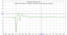
Yes, in the earlier measurements that Niklas sent the absolute phase ( polarity )
was inverted.
It was obvious to me after looking at his files IR trace ( of the woofers ) .
I don't where within his system, polarity has gotten flipped ( it could be anywhere ).
It's time for Nilkas to take a battery to his current speakers ( with wires un-hooked at the amp end ) apply a few volt battery and then look for outward cone movement of the woofers .
Hi Niklas,
Here's what I've done ( using your measurements > made in place ).
- A large Thanks! to Dissi for having previously provided some real world .zma files for these drivers.
- I ended up with a woofer offset of just over 1 inch ( 25mm ) using the curve-fitting method on two different files .
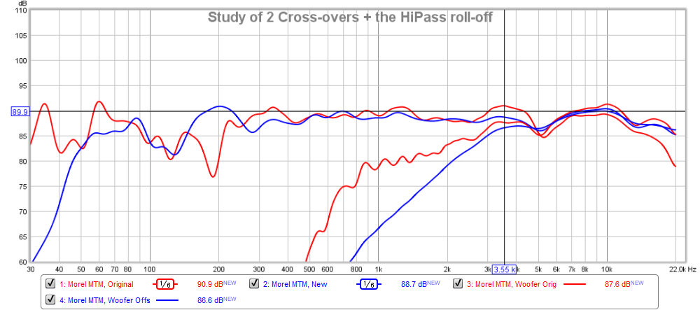
Let's start with a quick comparison of your original network and this effort .
(a) It's worth looking at how much more protection the tweeter gets ( from the newer network ) below 1K.
> The original is @ 10db down
> The newer would be @ 24db down ( at 1K )
(b) The "bumps" at 1,25K & 3.5K are reduced
(c) The trough at 5.2K has been filled a bit ( though to really fill it right in, you'll need to identify & fix the likely diffraction issue I previously brought-up ).
(d) I endevoured to maintain a similar overall sensitivity to what you currently enjoy > though this being somewhat smoother, it likely won't sound quite as loud.
(e) There's hardly any BSC in this network ( using your subs would fillin a lot of what might be missing ).
(f) If the tweeter level needs increasing ( especially if you start cranking the sub level ) > reduce the value of R1.
- start with going 1.5R and then go smaller if you still need more HF.

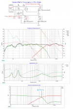
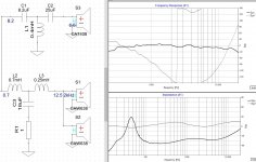
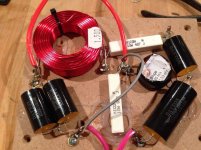
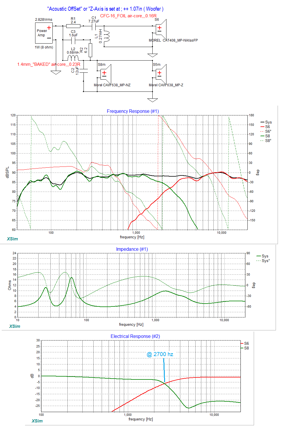
Here's the network ( with a study of it's different responses );
( it's a pretty large pic )
- it incorporates your existing parts into the new HiPass section.
- The LowPass section will require buying all new parts.
- L2 - the coil recommendation is in the pic ( as a Mundorf "Baked" wire-type air-core ).
- C2 at this point would be fine with a Mundorf, NP electrolytic
- C3 could easily be a Metallized Mylar type cap at that position ( & small size ).

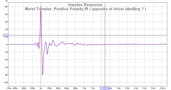
- Pay strict attention to the driver polarities here > they both need to be the same ( say positive for the sake of argument ) .
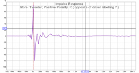
- Driver polarity can be determined by using REW and then looking at the IR of each driver.
For instance, this is what you sent me previously ( for the 2 woofers );
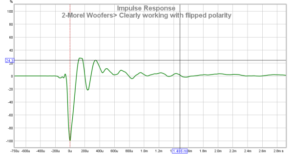
And here's the IR for a tweeter ( flipped according to the labelling on the driver > if I remember correctly )

Here's what I've done ( using your measurements > made in place ).
- A large Thanks! to Dissi for having previously provided some real world .zma files for these drivers.
- I ended up with a woofer offset of just over 1 inch ( 25mm ) using the curve-fitting method on two different files .
Let's start with a quick comparison of your original network and this effort .
(a) It's worth looking at how much more protection the tweeter gets ( from the newer network ) below 1K.
> The original is @ 10db down
> The newer would be @ 24db down ( at 1K )
(b) The "bumps" at 1,25K & 3.5K are reduced
(c) The trough at 5.2K has been filled a bit ( though to really fill it right in, you'll need to identify & fix the likely diffraction issue I previously brought-up ).
(d) I endevoured to maintain a similar overall sensitivity to what you currently enjoy > though this being somewhat smoother, it likely won't sound quite as loud.
(e) There's hardly any BSC in this network ( using your subs would fillin a lot of what might be missing ).
(f) If the tweeter level needs increasing ( especially if you start cranking the sub level ) > reduce the value of R1.
- start with going 1.5R and then go smaller if you still need more HF.
Here's the network ( with a study of it's different responses );
( it's a pretty large pic )
- it incorporates your existing parts into the new HiPass section.
- The LowPass section will require buying all new parts.
- L2 - the coil recommendation is in the pic ( as a Mundorf "Baked" wire-type air-core ).
- C2 at this point would be fine with a Mundorf, NP electrolytic
- C3 could easily be a Metallized Mylar type cap at that position ( & small size ).
- Pay strict attention to the driver polarities here > they both need to be the same ( say positive for the sake of argument ) .
- Driver polarity can be determined by using REW and then looking at the IR of each driver.
For instance, this is what you sent me previously ( for the 2 woofers );
And here's the IR for a tweeter ( flipped according to the labelling on the driver > if I remember correctly )
Attachments

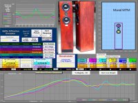
Basic Software sims of MTM using Morel CAW638 woofers and a Morel CAT408 tweeter. Morel datasheets were used.
For a MTM topology, BW3 - BW3 crossovers offer constant power and a wider center lobe polar pattern.
Software baffle SPL simulation shows a -dip around 2.7kHz and a +rise around 4kHz.
Software room simulation shows that placing the speakers near the back wall is necessary for enough room gain to cover most baffle step loss below 300Hz without some attenuation of the M and T.
Attachments
Hi LineSource,
It's nice to see a your interest in this thread.
Back in post#25 Dissi was kind enough to post the zma files for both of these two Morel drivers.
Once I plugged those "Z files" ( into my first posted "teaser" design ) I saw how much error I was baking into the design ( by simply using an impedance file grabbed from the manufacturers website ,> using tracing software > that doesn't generate any phase inforamtion ).
You might want to do the same ( use Dissi's files ) within your offering to then see how things glue together around the crossover point.
A couple of things that I've learned going through this process is that both REW and FPGraph Tracer can be unreliable partners due to some significant errors they want to inject into exported .frd files.
So far, I have gotten much much more out of this thread ( than say Niklas ) by being the guy who has to grapple with all these errors ( & it's still not over ).
cheers <.
Last edited:
This is all looking quite promising.
Below is a speaker called the Morel Duet.
Morel "Duet Fortissimo": Because I need another project! | Audiokarma Home Audio Stereo Discussion Forums
1.5mH and 8uF bass filter on single driver. About 3.3uF/0.25mH/10uF for 3 kHz XO with some attenuation.
How hard are these things?
Below is a speaker called the Morel Duet.
Morel "Duet Fortissimo": Because I need another project! | Audiokarma Home Audio Stereo Discussion Forums
1.5mH and 8uF bass filter on single driver. About 3.3uF/0.25mH/10uF for 3 kHz XO with some attenuation.
How hard are these things?
Attachments
In "IR Windows" check the "add Freq Dependent Window" and choose 6 as width in cycles > click "apply windows".
That is the more-or-less what many here are using as de-facto standard when measuring with REW. Nothing wrong with what you are doing though, but the above is more eye friendly and not less accurate.
Remember to check the phase (invert if needed) since the measurement looks like it was flipped somewhere (it's all at the ends of the graph...)
I find that setting and entered 6 cycles width but I see no "apply windows" anywhere.
Yes, in the earlier measurements that Niklas sent the absolute phase ( polarity )
was inverted.
It was obvious to me after looking at his files IR trace ( of the woofers ) .
I don't where within his system, polarity has gotten flipped ( it could be anywhere ).
It's time for Nilkas to take a battery to his current speakers ( with wires un-hooked at the amp end ) apply a few volt battery and then look for outward cone movement of the woofers .
Well, the polarity is correct by the drivers (except for the tweeters which is the other way around) and it should be correct at the filter too. I'll have a look at the binding posts, it could be flipped there but I doubt it. Do I need to make new measurements or can you flip the polarity somehow in REW?
Hi Niklas,
Here's what I've done ( using your measurements > made in place ).
- A large Thanks! to Dissi for having previously provided some real world .zma files for these drivers.
- I ended up with a woofer offset of just over 1 inch ( 25mm ) using the curve-fitting method on two different files .
Let's start with a quick comparison of your original network and this effort .
(a) It's worth looking at how much more protection the tweeter gets ( from the newer network ) below 1K.
> The original is @ 10db down
> The newer would be @ 24db down ( at 1K )
(b) The "bumps" at 1,25K & 3.5K are reduced
(c) The trough at 5.2K has been filled a bit ( though to really fill it right in, you'll need to identify & fix the likely diffraction issue I previously brought-up ).
(d) I endevoured to maintain a similar overall sensitivity to what you currently enjoy > though this being somewhat smoother, it likely won't sound quite as loud.
(e) There's hardly any BSC in this network ( using your subs would fillin a lot of what might be missing ).
(f) If the tweeter level needs increasing ( especially if you start cranking the sub level ) > reduce the value of R1.
- start with going 1.5R and then go smaller if you still need more HF.
Here's the network ( with a study of it's different responses );
( it's a pretty large pic )
- it incorporates your existing parts into the new HiPass section.
- The LowPass section will require buying all new parts.
- L2 - the coil recommendation is in the pic ( as a Mundorf "Baked" wire-type air-core ).
- C2 at this point would be fine with a Mundorf, NP electrolytic
- C3 could easily be a Metallized Mylar type cap at that position ( & small size ).
- Pay strict attention to the driver polarities here > they both need to be the same ( say positive for the sake of argument ) .
- Driver polarity can be determined by using REW and then looking at the IR of each driver.
For instance, this is what you sent me previously ( for the 2 woofers );

And here's the IR for a tweeter ( flipped according to the labelling on the driver > if I remember correctly )
No need to think about how loud the speakers go. I live in an apartment now and I'll be stuck in apartments for many years to come. This also means that I have sold my subs (well, I managed to sell two of my LAB12 drivers, still have another two left to sell).
How do I find the IR in REW?
Edit: Just checked the binding posts, they are wired correctly. I unplugged the cables from my amplifier and tested with a 9V battery and the cones moved out as they should.
Last edited:
Niklas,
I still have a lot of double-checking of my ( ad-hoc ) data before I can "green-light" a parts purchase.
Additionally, I've got at least 2-3 other filters to present as options ( just to confuse the picture ).
You'll need to wait before moving forward ( please ) until I return from my travelling ( which is next Monday night ) and am able to refocus on the job "at-hand" .
Niklas,
I still have a lot of double-checking of my ( ad-hoc ) data before I can "green-light" a parts purchase.
Additionally, I've got at least 2-3 other filters to present as options ( just to confuse the picture ).
You'll need to wait before moving forward ( please ) until I return from my travelling ( which is next Monday night ) and am able to refocus on the job "at-hand" .
Alright, as I said before, there's no hurry
Additionally, I've got at least 2-3 other filters to present as options ( just to confuse the picture )
I simulated a 2Khz BW3-BW3 crossover using the measured phase data instead of the S/W generated phase data. The CAD tools predict a sharper -dip around 2.7Khz from edge diffraction than the series of shallow -dips around 2kHz in your measurements. Early D'Appolito discussions favor BW3 because the main lobe was larger and had less tilt.
Have you simulated BW3-BW3 for this Morel MTM?
Attachments
I simulated a 2Khz BW3-BW3 crossover using the measured phase data instead of the S/W generated phase data. The CAD tools predict a sharper -dip around 2.7Khz from edge diffraction than the series of shallow -dips around 2kHz in your measurements. Early D'Appolito discussions favor BW3 because the main lobe was larger and had less tilt.
Have you simulated BW3-BW3 for this Morel MTM?
Hi LineSource,
I've simmed many a 3x2, 3x3, 2x2 parallel, 2x2 series, ie; many different combos actually.
Vernacular check: ( 3x2 = 3-pole HF over 2-pole LF ) for instance
I'm using .frd files derived from Niklas actual ( in box, in room measurements ).
ie; The bumps and suck-outs seen within my sims won't be going away, no matter how well the crossover region gets stitched together .
Here are the Fr's for three contenders ( from amongst dozens made ).
To recap, these use actual Fr's made by Niklas out in the middle of his living room ( once he places the speakers against their permanent wall location there is a measurable increase in bass response ).
Zma files were provided by Dissi ( Thanks ! )
I've displayed these sims using the WinPCD software so that the respective power responses could be compared ( XSim doesn't have that feature ).
Two of these are 3x3 networks, with the third being a 2x2.
Two of them sport them mild notching on the woofer.
All three have inline resistors in the HF section for level matching.
One of these designs is from LineSource ( Thanks ! )

Wednesday or Thursday of this week I'll post the schematics so that a "parts-count" for each, can be taken into consideration.
To recap, these use actual Fr's made by Niklas out in the middle of his living room ( once he places the speakers against their permanent wall location there is a measurable increase in bass response ).
Zma files were provided by Dissi ( Thanks ! )
I've displayed these sims using the WinPCD software so that the respective power responses could be compared ( XSim doesn't have that feature ).
Two of these are 3x3 networks, with the third being a 2x2.
Two of them sport them mild notching on the woofer.
All three have inline resistors in the HF section for level matching.
One of these designs is from LineSource ( Thanks ! )
Wednesday or Thursday of this week I'll post the schematics so that a "parts-count" for each, can be taken into consideration.
maybe not the best place to ask but I am going to do it.
I am looking to replace/upgrade components for my crossover speakers. The resistor are some ceramic classic look 10w and I would like to replace them with some 12 w MILLS Non-Inductive Wire Wound Resistors MRA-12 or some paralleled vishay CPF3 (4 or more) what do you think about that?
Please let me know your thoughts,
Gabe
You are in a similar position as the other day regarding capacitors. Resisors that you are likely to replace have the same impedance profile up to 20 kHz range as the more expensive ones, so audible changes on account of that will not happen, but it is an option to consider for those that find it worthwhile. Personally, I would rather have one Mills than a couple of Vishay's acting as one.
- Status
- This old topic is closed. If you want to reopen this topic, contact a moderator using the "Report Post" button.
- Home
- Loudspeakers
- Multi-Way
- New crossover for my current speakers