There are a lot of tricks to play with to get smooth TL output. Offsetting driver relative to closed end, having an expanding TL that ends in a mass loaded constriction helps too, as well as strategically placed stuffing. The advantage of TL is better cone motion control for lower distortion and sometimes more SPL from bass (more gain) often to point of offsetting baffle step loss. Try straight MLTL's with driver at 1/3 distance from closed end and terminus that is smaller.
There are a lot of tricks to play with to get smooth TL output. Offsetting driver relative to closed end, having an expanding TL that ends in a mass loaded constriction helps too, as well as strategically placed stuffing. The advantage of TL is better cone motion control for lower distortion and sometimes more SPL from bass (more gain) often to point of offsetting baffle step loss. Try straight MLTL's with driver at 1/3 distance from closed end and terminus that is smaller.
Will do.
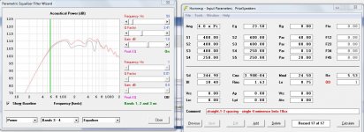
Here is my best attempt at doing what XRK recommends, decently seems smooth enough to work and rather simple shape, 3 bands of EQ applied, 52 L
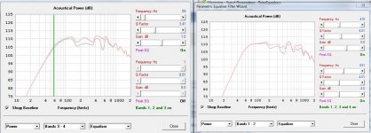
larger 75 L version, see second picture. Double cross sectional area and double the drivers to add 6 dB output.
larger 75 L version, see second picture. Double cross sectional area and double the drivers to add 6 dB output.
Attachments
Last edited:
I may be crazy but a part of me wants to try a 3012LF driver crossed at 1500 Hz. Any good reasons why I shouldn't? Main reason I'd like to is it allows 116 dB in 100L 4pi down to 50 Hz whereas the dual CX10 is 150L to do the same, only complication is adding a horn driver. I know it's a subwoofer driver but it appears that if crossed sufficiently low it should work just as well as (for example) a 3012 HO, just with 9 mm xmax.
See:
See:
Attachments
I may be crazy but a part of me wants to try a 3012LF driver crossed at 1500 Hz. Any good reasons why I shouldn't? Main reason I'd like to is it allows 116 dB in 100L 4pi down to 50 Hz whereas the dual CX10 is 150L to do the same, only complication is adding a horn driver. I know it's a subwoofer driver but it appears that if crossed sufficiently low it should work just as well as (for example) a 3012 HO, just with 9 mm xmax.
See:
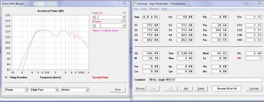
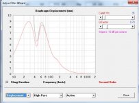
Here's the design.
Specs:
3012LF bass driver XOVER to PRV Audio D280Ti-S at 1600 Hz, 3rd or 4th order
5.4 cu ft external
F3 of 42 Hz
Highpass at 35
115 dB XMAX - 1m full space 1 speaker.
120 dB XMAX - 1m 2pi space if used as a subwoofer lowpass at 100-150 Hz 4th order.
Attachments
Last edited:
you could "rotate" the vent as below and see what happens
An externally hosted image should be here but it was not working when we last tested it.
Here's the design.
Specs:
3012LF bass driver XOVER to PRV Audio D280Ti-S at 1600 Hz, 3rd or 4th order
5.4 cu ft external
F3 of 42 Hz
Highpass at 35
115 dB XMAX - 1m full space 1 speaker.
120 dB XMAX - 1m 2pi space if used as a subwoofer lowpass at 100-150 Hz 4th order.
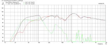
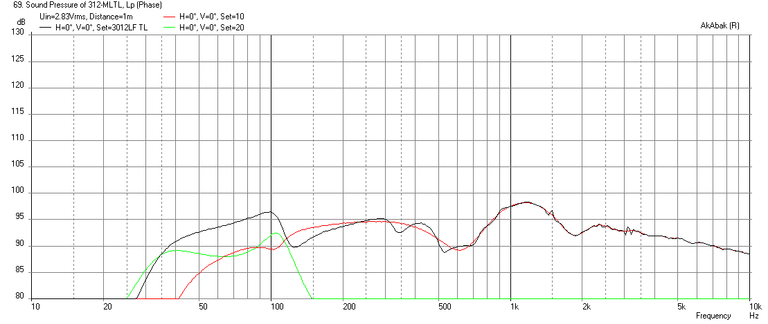
Here is an Akabak sim of the same geometry but with all the folds and turns included. Stuffing is used in the TL from closed end through the turn.
Sensitivity at 2.83v and 1m in 4pi space:

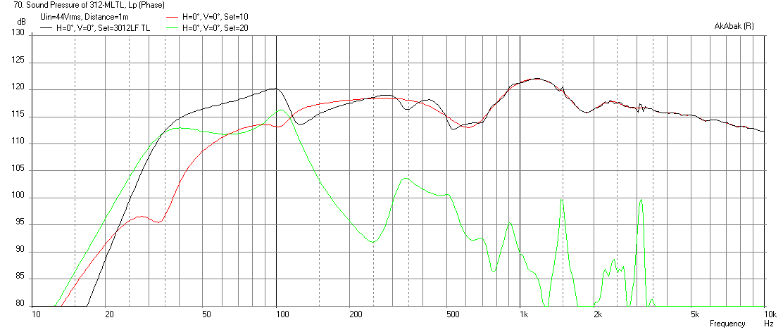
4pi at 44v to reach xmax (with 12dB 35Hz HPF):

2pi at 44v:
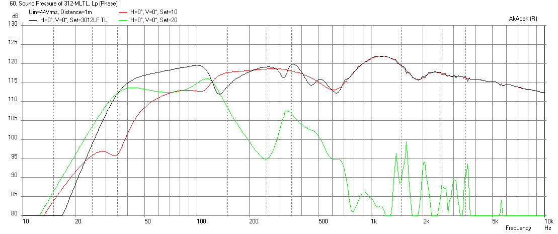
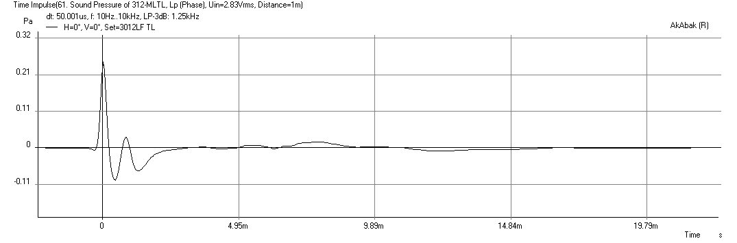
The notch at 135Hz can be reduced by moving the driver's position relative to the closed end. Also, due to the mismatch of the back wave and front wave, the cancellation dip at 135Hz also shows up as a double pulse in the impulse response:
Attachments


Here is an Akabak sim of the same geometry but with all the folds and turns included. Stuffing is used in the TL from closed end through the turn.
This is looking like a good start, although I'm not sure if all of my dimensions match yours as our simulations seem significantly different. Here are all the dimensions written out, just to double check: (all dimensions internal)
1st rectangular cross section:7.25 in deep by 16.5 in wide, driver center offset 7.25 in from beginning of line. This cross section continues, wrapping around the top piece for a total of 35.8 inches to the cusp of the horizontal line drawn by the back bottom edge of the port piece, followed by the bottom channel that on center (including the turn) measures 15 in.
Also, your sensitivity seems higher than mine but your excursion models higher at lower voltages, hmmm, may just be that since akabak takes into account geometry that it also plays a significant roll in above parameters.
Thanks a lot for putting it into the sim. What driver offset helps mitigate the 135 Hz dip the most? (which simulates to a 160-260 dip in my model).
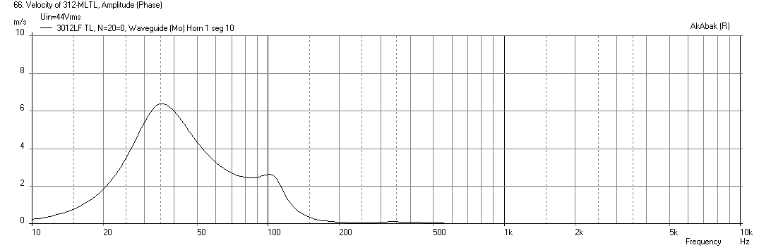
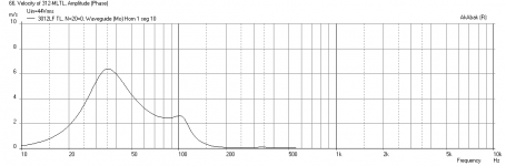
Just wondering, what is the air velocity at the terminus at 44V? It may just be me but it seems like if you take the voltage gain ratio of 44/2.83 -> 23.8 dB the output is getting reduced in multiple spots up to about 4 dB, what kind of effects are we seeing here that are reducing power at high output? Is the port too small? Are we seeing driver compression? Just seems a bit odd how non-linear the high level versus the low-level signal operates.
I went on your HR CSA and assumed a 14in wide internal width. From that I got a 9.34in deep TL and used the lengths from the HR model but added the 180 deg turn and 90 deg turn at the bottom. The vent is 5.61in high. Total cabinet height is 35.8in (not including wood thickness). To reduce the first dip, usually a 0.33x driver offset works well, but not always. You have to fine tune with the model. Your TL is more like a tapered one rather than a straight with a constriction. I think this may be the cause of the unusually large dip. Usually the constriction is 0.33x of Sd for a typical MLTL. Very similar to sizing a port for BR. However I think your larger vent makes it more efficient - but lets more harmonic ripples come through.
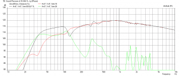
Not sure why you think behavior at low power vs high power is not consistent. Might be because I showed low power at 4pi and high power at 2pi? Compression effects are not modeled in Akabak. But for your huge vent, there is not issue as velocity at 44v is below 10m/s:
Here are the segments of the TL that I modeled. Sc is scaling factor=1 (ignore) numbers are in inches multipled by 0.0254 to get meters. Width is 14in x S_throat or S_mouth to get CSA:
The Akabak script is attached if anyone wants to play with it.
Not sure why you think behavior at low power vs high power is not consistent. Might be because I showed low power at 4pi and high power at 2pi? Compression effects are not modeled in Akabak. But for your huge vent, there is not issue as velocity at 44v is below 10m/s:
Here are the segments of the TL that I modeled. Sc is scaling factor=1 (ignore) numbers are in inches multipled by 0.0254 to get meters. Width is 14in x S_throat or S_mouth to get CSA:
Code:
| Define TL Segments (need to multiply by Width for area): S_Throat, S_Mouth, Length

	S1T=9.34*Sc*0.0254;	S1M=9.35*Sc*0.0254;	L1=17.40*Sc*0.0254;  | closed end to driver
 	S2T=9.35*Sc*0.0254;	S2M=9.36*Sc*0.0254;	L2=12.1*Sc*0.0254;   | driver to turn
	S3T=9.36*Sc*0.0254;	S3M=13.2*Sc*0.0254;	L3=4.67*Sc*0.0254;  | turn 90 deg expansion
	S4T=13.2*Sc*0.0254;	S4M=9.34*Sc*0.0254;	L4=4.67*Sc*0.0254;  | turn 90 deg contraction
	S5T=9.34*Sc*0.0254;	S5M=13.2*Sc*0.0254;	L5=4.67*Sc*0.0254;  | turn 90 deg expansion
	S6T=13.2*Sc*0.0254;	S6M=9.34*Sc*0.0254;	L6=4.67*Sc*0.0254;  | turn 90 deg contraction
	S7T=9.34*Sc*0.0254;	S7M=9.35*Sc*0.0254;	L7=26.4*Sc*0.0254;  | long straight down back
	S8T=9.35*Sc*0.0254;	S8M=10.78*Sc*0.0254;	L8=2.80*Sc*0.0254;  | turn at mouth 90 deg expansion

	S9T=10.78*Sc*0.0254;	S9M=5.61*Sc*0.0254;	L9=4.67*Sc*0.0254;  | turn 90 deg contraction
	S10T=5.61*Sc*0.0254;	S10M=5.62*Sc*0.0254;	L10=9.34*Sc*0.0254; | final terminus exit
The Akabak script is attached if anyone wants to play with it.
Attachments
Last edited:
I went on your HR CSA and assumed a 14in wide internal width. From that I got a 9.34in deep TL and used the lengths from the HR model but added the 180 deg turn and 90 deg turn at the bottom. The vent is 5.61in high. Total cabinet height is 35.8in (not including wood thickness). To reduce the first dip, usually a 0.33x driver offset works well, but not always. You have to fine tune with the model. Your TL is more like a tapered one rather than a straight with a constriction. I think this may be the cause of the unusually large dip. Usually the constriction is 0.33x of Sd for a typical MLTL. Very similar to sizing a port for BR. However I think your larger vent makes it more efficient - but lets more harmonic ripples come through.
Not sure why you think behavior at low power vs high power is not consistent. Might be because I showed low power at 4pi and high power at 2pi? Compression effects are not modeled in Akabak. But for your huge vent, there is not issue as velocity at 44v is below 10m/s:
Here are the segments of the TL that I modeled. Sc is scaling factor=1 (ignore) numbers are in inches multipled by 0.0254 to get meters. Width is 14in x S_throat or S_mouth to get CSA:
Code:| Define TL Segments (need to multiply by Width for area): S_Throat, S_Mouth, Length S1T=9.34*Sc*0.0254; S1M=9.35*Sc*0.0254; L1=17.40*Sc*0.0254; S2T=9.35*Sc*0.0254; S2M=9.36*Sc*0.0254; L2=12.1*Sc*0.0254; S3T=9.36*Sc*0.0254; S3M=13.2*Sc*0.0254; L3=4.67*Sc*0.0254; S4T=13.2*Sc*0.0254; S4M=9.34*Sc*0.0254; L4=4.67*Sc*0.0254; | contraction S5T=9.34*Sc*0.0254; S5M=13.2*Sc*0.0254; L5=4.67*Sc*0.0254; S6T=13.2*Sc*0.0254; S6M=9.34*Sc*0.0254; L6=4.67*Sc*0.0254; | contraction S7T=9.34*Sc*0.0254; S7M=9.35*Sc*0.0254; L7=26.4*Sc*0.0254; S8T=9.35*Sc*0.0254; S8M=10.78*Sc*0.0254; L8=2.80*Sc*0.0254; S9T=10.78*Sc*0.0254; S9M=5.61*Sc*0.0254; L9=4.67*Sc*0.0254; | contraction S10T=5.61*Sc*0.0254; S10M=5.62*Sc*0.0254; L10=9.34*Sc*0.0254;
Looks like I screwed up my solidmodel, the "constriction" section starts at the last 90 degree bend, else the rest is a consistent 7.25 inch channel as drawn (may increase this to 8 soon).
My internal width is probably going to be 16-18 inches internal.
I figured out why the plots look different, one is limited by XMAX (driven to thermal rating of driver where XMAX isn't reached) and the other is normal 2pi version. Still seems like the gain is a little off. I would expect ~4-6 dB+ voltage gain ratio of 23.8 dB = 28-30 dB higher plot at 2pi 44V compared to 4 pi 2.83 V in the low end.

Here is SPL in 2pi at 2.83v and 44v. I get 24dB difference like you predict.
2.83v:
44v:
I guess I got confused because in the previous post that "2.83 V 2pi" chart was labeled as 4pi/ 1 m.
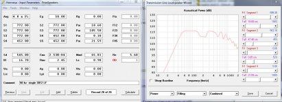
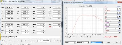
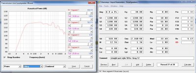
Regardless, I had to update my hornresp based on the solidworks model as I didn't correctly follow the hornresp CSA's. Here is the updated hornresp based on the solidmodel:
Also, I've attached a 2.83V,44 V @4pi comparison with the updated hornresp model. Hornresp has the excursion peaking at 8 mm using 44vin and 9.1 mm (xmax) at 50vin.
The discrepancies we're having could very well be that my simulation has no high-pass and yours probably does, I plan on using a 40 Hz HP 4th order BW.
Attachments
Last edited:
Yes, I applied 12dB HPF at 35Hz per your notes in previous post. HR and Akabak usually are very close in SPL prediction. We may have something off. Note that you want to use as low of an order HPF as you can get away with. The higher the order, the higher your phase shift and group delay is. 4th order is probably not necessary.
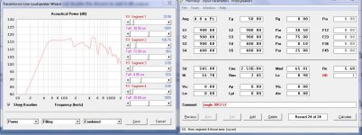
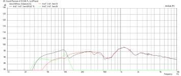
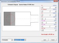
Here is the updated response, 35 Hz general 2nd order .707 Q.
New system F3 is 52 Hz shifted up by the smaller CSA/different constriction definition, still better than I hoped.
New system F3 is 52 Hz shifted up by the smaller CSA/different constriction definition, still better than I hoped.
Attachments
Last edited:
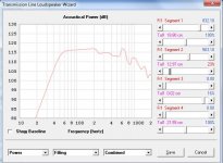
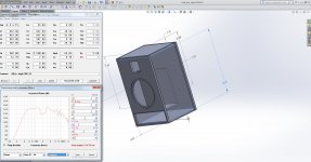
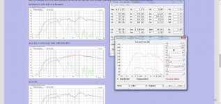
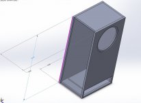
Redesigned as straight shot (16x12 internal cross section, inches). With a lot of stuffing behind the driver and sparse to none below it looks quite good.
Re-simulated, to match SolidWorks dimensions. Question, how do I make the constriction behave more like a transmission line and less like a port? I'm thinking that air flow will still be under 10 m/s with this new driver/orientation but I'd like to check it. Also, would there be a benefit to putting a diagonal corner piece to direct energy away from the "dead corner" right above the "port". The internal "port" dimension is 3x16.5 inches, all other important dimensions can be obtained from the picture/hornresp plot.
Attachments
Last edited:
- Status
- This old topic is closed. If you want to reopen this topic, contact a moderator using the "Report Post" button.
- Home
- Loudspeakers
- Multi-Way
- Designing a 2 Way Transmission Line