It seems that no one has mentioned the higher compression ratio of the old (skool) JBL 24 .. drivers as a possible cause of the duck noise at high SPL.
DJK (RIP) may not have been completely wrong in his assessment. Modern (pancake) drivers have a much lower compression ratio than the old heavyweights.
Even today, 2380 (clones) are used in highly regarded 2-way speaker systems. The Strauss MF2 (now MF2.2) and Tony Gee's Calpamos are 2 examples.
From my research the Strauss has crossed the table of Mastering Engineer and I haven't come across any complaints....that says a lot.
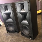
A pair of 2360's came in the mail today which I will be compared to the 2380a, some time in the future. As I look at the off axis charts, they are are good representatives of two different polar styles. I can't help but wonder about the Strauss's high regard vs the flat off axis response of the 2380....
Attachments
Last edited:
Last edited:
2360s... by mail? 😱 😀
Omg not the 60's....the fricken 2386's.......
Rob, do you have experience with the 2352?
It is arguably one of the best JBL horns ever.
Hello Ro808
No I have a personal preference for the shallow 100x100 horns/wavequides. Never tried it although Zilch the mad dabbler probably did. Take a look in the Quick and Dirty 4430 thread. I think he tried everything he could get his hands on in that thread!🙂
Rob🙂
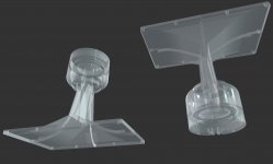
Used as intended, to go from a 1.5" exit to 2" works OK. If used in reverse, lots of reduction in fidelity.A 2" to 1.5" adapter....is this a fidelity no no?
This is one thread, but he posted many interesting posts on his Econowave-style experiments.
At that time - around 2006, he stated the 2352 was the best horn he had, and he had many (probably 80% or more of all horns ever produced by JBL).
At that time - around 2006, he stated the 2352 was the best horn he had, and he had many (probably 80% or more of all horns ever produced by JBL).
Attachments


Take a look in the Quick and Dirty 4430 thread.
Rob🙂
- Quick & Dirty 4430-Inspired Contents
- Quick & Dirty 4430-Inspired Two-Ways Part I
- Quick & Dirty 4430-Inspired Two-Ways Part II
Camplo, these links belong in your thread as well, I think.
Last edited:
Love it, the studio world needs to know this approach, a 3 way doesn't really cost that much....if you are smart...my KRKv4s4 on top of homemade v12's said so.....oops, I mean my 2 way with stereo subs....😛
Simulation of HOMs in 120° x 60° Diffraction Horn
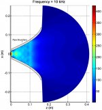
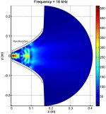
Below are some images of the Steady-State Analysis of a 120° x 60° diffraction horn with Simplified Excitation Signals.
This horn is similar to a JBL 2382, except for its depth: 30.48 cm (12") versus 23.495 cm (9 1/4″) for the JBL 2382.
Comment:
Although pipe modes and cutoff frequencies can be very different than those for a similar length horn, their analytical analysis is helpful as a horn can be thought of as a composition of several very small-length pipes. As the radius of the pipe gets larger, the amount of evanescence imposed on higher-order modes decreases. Thus, the amount of higher-order modal decay caused by a pipe will be larger than that caused by a horn. The figures show the magnitude of the interior pressure field for both cross sections of the 120° x 60° horn. The 120° cross section is similar to a pipe for the beginning portion of its geometry and prevalent decay of higher-order modes are observed at and below 10 kHz. In contrast, the 60° cross section opens up very quickly and higher order modes contribute much sooner. Significant amounts of higher-order modes appear to propagate much farther down the length of the horn for the 60° cross section even at 4 kHz.
As seen in the figures, higher-order modes are seen to be computationally insignificant at a frequency well below the cutoff frequency for the first higher-order mode where only the plane-wave mode contributes to far-field pressure radiation. Although higher order modes do not evanesce as much within a horn, a similar phenomenon is observed. The 120° x 60° horn agrees with the experimental measurement at higher frequencies, likely because of the pipe-like effects of the first half of its geometry, causing more rapid higher-order evanescence.
Higher-frequency disagreement may also be a manifestation of the incorrect representation of physical excitation source. The excitation source used in the BE simulations is piston like where a physical diaphragm would break up into modes, coincidentally, at frequencies around the cutoff frequency for higher-order pipe modes. As a result, when the excitation signal is well below the cutoff frequency, such that experimental measurement and numerical simulation are reduced to single-mode propagation, simulation and experiment agree. Otherwise, the simulation cannot accurately assign relative amplitude and phase to propagating pipe modes, without an accurate displacement profile for the diaphragm, which results in incorrect far-field pressure predictions for higher frequencies.
Attachments
-
 Pressure magnitude of the interior pressure field along the 120° cross section at 4 kHz.jpg254.3 KB · Views: 264
 -
 Pressure magnitude of the interior pressure field along the 120° cross section at 10 kHz.jpg239.3 KB · Views: 264
 -
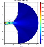 Pressure magnitude of the interior pressure field along the 120° cross section at 16 kHz.jpg270.3 KB · Views: 264
 -
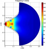 Pressure magnitude of the interior pressure field along the 60° cross section at 4 kHz.jpg318.8 KB · Views: 254
 -
 Pressure magnitude of the interior pressure field along the 60° cross section at 10 kHz.jpg279.1 KB · Views: 165
 -
 Pressure magnitude of the interior pressure field along the 60° cross section at 16 kHz.jpg302.2 KB · Views: 164
Last edited:
Hiya Ro808In addition, some Japanse "discovered" the throat of the 2380 is too short to properly match the deep exit section (with a low flare rate) of the old JBL drivers, which are basically WE594A/JBL375 derivatives. They fabricated a throat extension and I've posted the measurement results here.
Is there any more information about this adapter available?
To all:
I am debating fitting some JBL 2450 with their snouts removed onto JBL 2380A flares. They have a 1.5" exit, meant to be planar wave, supposedly similar to 2450SL. I will have to replace the snouts with an adapter plate at minimum, as the bolt pattern remaining after the snout is removed is about 137mm diameter. I can 3d print and later, have made in Alu, another snout adapter but I am struggling to find clear clues about how i should best match 1.5" to the entry of a 2380A flare (which should be monotonically increasing in area along its length, but clearly decreases in one axis first).
I would first try a conical adapter, to match with my best information so far - 2380A throat entry of around 25degrees, or 36deg per the FaitalPro HF201 used in HHH Calpamos.
Last edited:
Nevermind!
I've asked before, and you did provide!
I've asked before, and you did provide!
As it appears (it took me way too long time to dig up the blog post), those guys actually completely modified the 2380 using wood and filler.
The P-Audio 1.5>2" adapter is the only commonly available adapter that should work. It's more or less identical to the 2450J's snout and the throat section of the old 244.. family.
The P-Audio 1.5>2" adapter is the only commonly available adapter that should work. It's more or less identical to the 2450J's snout and the throat section of the old 244.. family.
- Home
- Loudspeakers
- Multi-Way
- JBL2380A, myth busting!