Hi everyone,
I am building a floorstanding 3 way speaker. My goal is to use the spare drivers that I have in hands and don't try to get great results (I understand that it is not possible with my current skills and with the drivers that I am going to use)
Need some assistance from someone who can help to design a bandpass filter for my midrange. The problem is that driver has no specs (small parameters)
It is a 5" sealed Sony Genuine Midrange Speaker. Bought it couple of years ago from ebay. Only thing I know is the impedance 8 ohms and 15 watts maximum power handling (written on the back of the speaker)
Looks very similar to this model from Goldwood:
https://www.parts-express.com/goldwood-gm-35-5-cone-midrange--280-012
I am going to use it together with double 8" woofer (https://www.parts-express.com/grs-8pr-8-8-poly-cone-rubber-surround-woofer--292-428) and Titanium dome tweeter (Bought from ebay, do not know specs except impedance 4 ohms)
My enclosure is ready and all i need is to connect the drivers to crossover network.
1)
Can anyone advice a crossover network for the frequency range 1.2 khz-8khz taking into consideration that the sensitivity can be 3-4 db greater that the sensitivity of my woofers.
2)
Is it possible to use different order filters for midrange, tweeter and woofer?
Any Assistance appreciated.
There's no easy answer for this one, without any measurements we can't give you any solution, even a wild stab in the dark will be massively wrong, guaranteed, and building by ear is fraught with problems.
What are your goals? I presume you enjoy both audio and DIY, in which case I'd recommend you buy a measurement mic and build a jig to measure impedance with your PC, that will at least get you close enough.
If you just want to build something cheap, sell it all and buy some finished speakers on ebay, they'll be better than anything you can build with what you have whilst you don't have measurements.
Sorry if that's not the answer you wanted.
Dear Nannoo,
Thank you for your reply.
I do understand that the result is not going to be good enough, My goal as I have stated above is to utilise what I have in hands. I have already build my enclosure, so I do not think that selling my current drivers is an option. I know that it is very hard to design a good crossover network and I also understand that it is difficult to get the best outcome out of my midrange driver taking into consideration that I do not have parameters.
I have some old equipment for measurement such as frequency generator, tester, mic, but that is all I have.
First thing that came to my mind was to buy and use a custom build crossover, but I can not find a suitable one with desired crossover points and impedance requirements for each driver slot.
Probably the easiest way for you, is to buy a 3-way crossover.
The most electronic-dealers have several types of crossovers normally used for car-hifi.
As long as you will only bring the speakers to life this could be an easy option for you.
With this type of crossover you can realise the complete speaker and afterwards you can measure if this is ok for you. For example Visaton have some well done crossovers.
If you want better results the next step should be to buy a complete speaker-kit")
The most electronic-dealers have several types of crossovers normally used for car-hifi.
As long as you will only bring the speakers to life this could be an easy option for you.
With this type of crossover you can realise the complete speaker and afterwards you can measure if this is ok for you. For example Visaton have some well done crossovers.
If you want better results the next step should be to buy a complete speaker-kit
Probably the easiest way for you, is to buy a 3-way crossover.
The most electronic-dealers have several types of crossovers normally used for car-hifi.
As long as you will only bring the speakers to life this could be an easy option for you.
With this type of crossover you can realise the complete speaker and afterwards you can measure if this is ok for you. For example Visaton have some well done crossovers.
If you want better results the next step should be to buy a complete speaker-kit
Worst.Advice.Ever.
This won't work. You don't know the impedance of each driver. You don't know the sensitivity. You don't know the frequency response. There's a million possible out comes and about 1% of them will be half useable.
Let's focus on what we can do... presuming you don't want to make an impedance plot with your computer, if you have a signal generator/tone generator you can measure the AC voltage drop across the driver and compare this to the drop across a resistor wired in series with a known value. Do this at the crossover frequencies (i.e. 350, 35000) for extra laziness and we can take it from there... but it's still going to be a bodge job...
Ok, here is what I know about my drivers.
I know the full specs, small parameters of my woofers for low frequencies
I know the impedance and power handling of my sealed midrange driver (I may assume it's frequency response may be around 600-1200hz like other sealed 5" drivers, that's why I want crossover points of 1.2khz-8khz to cover this range)
I know the imedance of my tweeter. Its frequency response I assume will be as other dome tweeter around 3khz-20khz. I have heard that it is not recommended to cross over the metal dome tweeters below 4-5khz, that's why I want to cross over it at 8khz to be in the safe side.
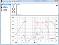
I can not use online 3 way calculator because they do not give me an option to chose the desired bandpass frequency range. All of the calculators require require only one of the crossover points, the other one defines by calculator itself. I tried one and input high crossover frequency, and it defined the low crossover frequency itself, pre defined 8:3 octaves.(attached) Also I know that all of the crossover networks uses resistors to protect midrange driver and tweeter and also to attenuate them.
Does it change the crossover points if used in series between filter and driver? What is the difference if u use resistors before filter or in between the filter and driver?
My plan is to use online 2 way crossover calculator to build 2nd order high pass and low pass filters for my tweeter and woofers, then to use the same calculator to find the values for bandpass filter. As far as I understood, bandpass filter is one high pass and one low pass filters connected in series (correct me if I am wrong)
I know the full specs, small parameters of my woofers for low frequencies
I know the impedance and power handling of my sealed midrange driver (I may assume it's frequency response may be around 600-1200hz like other sealed 5" drivers, that's why I want crossover points of 1.2khz-8khz to cover this range)
I know the imedance of my tweeter. Its frequency response I assume will be as other dome tweeter around 3khz-20khz. I have heard that it is not recommended to cross over the metal dome tweeters below 4-5khz, that's why I want to cross over it at 8khz to be in the safe side.
I can not use online 3 way calculator because they do not give me an option to chose the desired bandpass frequency range. All of the calculators require require only one of the crossover points, the other one defines by calculator itself. I tried one and input high crossover frequency, and it defined the low crossover frequency itself, pre defined 8:3 octaves.(attached) Also I know that all of the crossover networks uses resistors to protect midrange driver and tweeter and also to attenuate them.
Does it change the crossover points if used in series between filter and driver? What is the difference if u use resistors before filter or in between the filter and driver?
My plan is to use online 2 way crossover calculator to build 2nd order high pass and low pass filters for my tweeter and woofers, then to use the same calculator to find the values for bandpass filter. As far as I understood, bandpass filter is one high pass and one low pass filters connected in series (correct me if I am wrong)
Attachments
Ok, here is what I know about my drivers.
I know the full specs, small parameters of my woofers for low frequencies
I know the impedance and power handling of my sealed midrange driver (I may assume it's frequency response may be around 600-1200hz like other sealed 5" drivers, that's why I want crossover points of 1.2khz-8khz to cover this range)
I know the imedance of my tweeter. Its frequency response I assume will be as other dome tweeter around 3khz-20khz. I have heard that it is not recommended to cross over the metal dome tweeters below 4-5khz, that's why I want to cross over it at 8khz to be in the safe side.
I can not use online 3 way calculator because they do not give me an option to chose the desired bandpass frequency range. All of the calculators require require only one of the crossover points, the other one defines by calculator itself. I tried one and input high crossover frequency, and it defined the low crossover frequency itself, pre defined 8:3 octaves.(attached) Also I know that all of the crossover networks uses resistors to protect midrange driver and tweeter and also to attenuate them.
Does it change the crossover points if used in series between filter and driver? What is the difference if u use resistors before filter or in between the filter and driver?
My plan is to use online 2 way crossover calculator to build 2nd order high pass and low pass filters for my tweeter and woofers, then to use the same calculator to find the values for bandpass filter. As far as I understood, bandpass filter is one high pass and one low pass filters connected in series (correct me if I am wrong)
Mark,
This is very frustrating. Take some time to go and read and learn, what you have learned thus far seems muddy at best.
Impedance varies with frequency. This effects how different frequencies divide up and travel through the crossover network. Using a nominal figure won't get you very far at all, often at cross frequency you'll find impedance is low, i.e. 5.7ohms. Any midrange will go down to 350 Hz easily. A simple and good rule of thumb for 3-way systems is to crossover at 10x the lower frequency, or vice versa. 350 and 3.5kHz are very widely used and respected, with good reason.
There's nothing wrong with crossing a metal dome tweeter low, but id depends on the order of the xo and how good the tweeter is, you may play it safe and go for 400/4000Hz xos.
Online calculators won't get you anywhere good.
If you're going to ask for advice best to show you're listening to it by doing something about it, otherwise go and build terrible speakers
Not trying to sound nasty but you're not doing yourself any help here.
Sorry to say Mark that those sealed back midrange drivers never ever sound any good when used in the preferred midrange of 300 to 3000hz. Most of them have an Fs of about 150 or higher and to avoid any back wave from the metal rear they must be crossed a minimum of two octaves above that resonance and a first order high pass isn't enough
Think of them as being a decent cone tweeter and you have a better understanding of how they are usually used.
I understand that you want to use the drivers you already have but speaking as a bloke who started building speakers exactly as you want to the effort isn't worth the end result.
It is possible to retro fit your box with a separate midrange enclosure, either a purchased plastic unit or a re-purposed empty coffee tin but the best advice you will get here is to buy a decent [cheap] proper midrange, design the bandpass for the mid and then play with the XO for the bass
I hope the box you have already built is big, I just did a quick calculation in my head and those woofers need a box bigger than 90 liters and that will be fully stuffed, bigger would be better
Pictures of the mids will help, it may be one i have already on my shelf of spare bits
I don't recognise the country flag; where are you located and where is your best source of drivers?
Last edited:
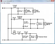
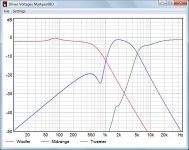
These sealed midrange drivers have a terrible resonance peak, which has to be equalized in the crossover by all means, otherwise the result is not be very pleasant indeed.
There are many unknowns in this speaker project, which make a proper crossover design difficult. Nevertheless I do attach a possible solution. It's as best I could and shouldn't be completely wrong IMO.
There are many unknowns in this speaker project, which make a proper crossover design difficult. Nevertheless I do attach a possible solution. It's as best I could and shouldn't be completely wrong IMO.
Attachments
Hi,
Its quite depressing when people try to sling all the wrong
drivers together and expect the thing to work via the x/o.
How ever lets try in some sort of sense. 1KHz sounds
reasonable bass to mid, use a first order series using
8 ohm values. Listen to it with no tweeter and judge
what midrange phasing works best, I have no idea.
If the presence region is strident add a series resistor
or L-pad values to get a relatively dark sound.
Then cascade a first order series x/o off the mid
drive for the mid and treble. Again assume 8 ohm
and play with the x/o point and tweeter phase.
Add a series resistor or L-pad values to the tweeter
if it seems too dominant in the scheme of things.
5KHz+ I'd guess is the likely ballpark. Perhaps
lower if the mid is run full level and sounded dark.
You will have something via some sort of method,
that is more sensible than just guessing, and better
than an off the shelf clueless x/o, but a very rough
implementation, but TBH your drivers don't deserve
much better unless you have measurements and
can make more informed decisions about the x/o.
(FWIW the bass drivers will do some form of crude
BSC in their sealed boxes, and here it is ignored.
However an option is a 3.something way. Which
is a 0.5 way inductor* across the lower unit based
on the baffle width bypassed by a 8R resistor
to reduce the full BSC compensation. Such an
arrangement will vary the mid and treble levels.)
rgds, sreten.
* If bypassed the resistor will halve
inductor value based on baffle width.
(A crude approximation with a single value.)
FWIW 1st order cascaded series although they
are rubbish in most real respects, at least handle
driver impedance peaks and inductance rise
far better than 1st order parallel does.
Hence known as quasi 2nd order.
Last edited:
FWIW 1st order cascaded series although they
are rubbish in most real respects, at least handle
driver impedance peaks and inductance rise
far better than 1st order parallel does.
Hence known as quasi 2nd order.
The idea did cross my mind as well, it's a more robust way to attempt to handle unknown quantities.
But not knowing the specs, and with the midranges looking more like tweeters, this project is looking more like a knightmare... unless you use it as a learning exercise of course. Still don't know if this is for fun or to try to save money or what...
- Status
- This old topic is closed. If you want to reopen this topic, contact a moderator using the "Report Post" button.
- Home
- Loudspeakers
- Multi-Way
- Bandpass Filter for a Sealed Midrange