Novel Open Baffle Construction w/ Slot Loaded Woofers
Been building open baffle dipole loudspeakers since 2009. Inspired by Linkwitz, Martin J King and John Kreskovsky, an idea always starts as "I could just make holes in a board and... poof- I would have a OB panel that would look like an electrostatic once a grill was on." Each time the reality was much harder: after a support structure and a box for the bass radiators was designed, it morphed into a much more ambitious project. Then, after countless weekends of woodworking & finishing, each project would end with tendonitis in my elbows and MDF dust in my sinus tract and eyes. (Never had any energy left to finish a grill on any project.) Each time my friends were amazed with the open sound, but the measurements were not as good as I wanted (I keep getting more picky about the directivity). Rinse and repeat.

Woofer Directivity
The various iterations left me with know how concerning cut-outs in the baffle to shape the directivity, constrained layer damping (CLD) to lower baffle vibration and shaping the rear of a U-frame to minimize resonance. My wife was pressing for something smaller (and with less wires!) With my elbows recovered last Spring I tried again. At one point, I had purchased about 80 Aura/ NS6-255-8A woofers for $6 each after finding them to have a surprisingly linear motor. Using these in the slot-loaded OB woofer concept that Nelson Pass had documented in conjunction with a small U-frame, a reasonably small OB concept emerged. The force-canceling of the slot set-up would minimize vibration from the woofers which was always unsettling in previous designs.
I decided to get all of the parts CNC cut; finishing would be limited to just a spray coat of clear shellac. Then it would be just assembly and wiring- able to be done in just a couple of weekends. The grill would be integrated into the design with fabric stretched over the baffle. Instead of a stack of external amps and a DSP crossover, I would spring for Hypex AS2.100d modules (a DSP crossover and bi-amp plate amp) and integrate them into the speakers.

Exploded View
The results were so good, especially with respect to lowering the effort, I thought that others would be interested in how these went together. So here's how it went-
The idea was to get all of the parts for one speaker cut from a single sheet of 1/2 inch MDF. This allows the CNC to cut all from one side in one pass (no need to turn over the pieces and register them for cuts on the backside), so the cutting cost is low. The front baffle is a lamination of two of the 1/2 inch parts sandwiched over a viscoelastic layer to form a 1.06" (27mm) thick baffle. The woofer slot assembly is glued into the baffle. The rear U-frame box bolts on to the baffle/slot assembly and holds the Hypex modules. (See exploded view.)

All from one sheet of MDF
An ME I work with helped me develop the SolidWorks 3D model one Saturday afternoon from sketches. Construction was indeed completed in a couple of weekends, measurement and tuning of the Hypex crossovers was perfected over a few more days. They looked so good in just clear shellac that I still have yet to install the grill fabric- LOL.
The midrange section is a 1-1/2 way setup using two 3-1/2" Vifa/TC9-FD-18-04 (with a 1.3mH inductor in series with the top one). The tweeter is a Vifa/OX20SC00-04 in a waveguide robbed from a Nuance/TW5-073LR; this combination has very constant directivity above 4kHz but the Vifa mids sounded so good equalized to 20kHz, that I never put in the effort to build the crossover for the tweeter- so right now it's "justfa show". The slot loaded woofer is made using eight NS6-255-8As for a total radiating area (Sd) of 1088sq-cm, about the same area as a 20" woofer!

On Axis Response
The overall results were impressive, especially considering the total cost was under $1,000 for a pair, complete with electronics. The Hypex modules are a bit pricy, but they have analog, SPDIF & USB inputs and dedicated (stereo or mono) subwoofer outputs (if you really NEED that last bottom octave). And you can switch inputs and control volume with an IR remote. The system is a complete stereo without the rack. My son uses his iPod as a source, I listen using my laptop as the source.

MF-HF Directivity
I will let the data speak for itself, but everyone who has heard them has been impressed with the rock solid imaging and tonal balance. I was slightly disappointed with a "shoulder" in the directivity plot around 1.3kHz, but overall it's very good. Response is +/-2dB from 35-20kHz on axis except for a 3.5dB dip around 1.3kHz that's on purpose. The true standout though, is the bass; the directivity is an almost perfect dipole as the outdoor measurements below show (un-gated, 2m ground bounce). A double bass, cello or a kick drum sounds like it's in the room, really. The speakers don't get at all muddy if you want to listen to Slipknot (which I don't). Toms hit you in the chest. You can feel no bass vibration in the baffle, the woofer force-canceling really works. Mid frequency vibration in the baffle is very low, the damping layer works.

Baffle before shellac & drivers.
Notice black line on the edge- it's the damping layer.
What do you think it is?
As for the construction- I am never going to cut another board again unless it's for a test baffle. Everything fit perfect and tooling holes made the alignment of the parts during gluing a breeze. The damping layer was a bit of a challenge to trim, but still easy in the light of past projects.

Done in two weekends- ready to tune.
Looking forward to comments. I have more data/pictures.
Been building open baffle dipole loudspeakers since 2009. Inspired by Linkwitz, Martin J King and John Kreskovsky, an idea always starts as "I could just make holes in a board and... poof- I would have a OB panel that would look like an electrostatic once a grill was on." Each time the reality was much harder: after a support structure and a box for the bass radiators was designed, it morphed into a much more ambitious project. Then, after countless weekends of woodworking & finishing, each project would end with tendonitis in my elbows and MDF dust in my sinus tract and eyes. (Never had any energy left to finish a grill on any project.) Each time my friends were amazed with the open sound, but the measurements were not as good as I wanted (I keep getting more picky about the directivity). Rinse and repeat.
Woofer Directivity
The various iterations left me with know how concerning cut-outs in the baffle to shape the directivity, constrained layer damping (CLD) to lower baffle vibration and shaping the rear of a U-frame to minimize resonance. My wife was pressing for something smaller (and with less wires!) With my elbows recovered last Spring I tried again. At one point, I had purchased about 80 Aura/ NS6-255-8A woofers for $6 each after finding them to have a surprisingly linear motor. Using these in the slot-loaded OB woofer concept that Nelson Pass had documented in conjunction with a small U-frame, a reasonably small OB concept emerged. The force-canceling of the slot set-up would minimize vibration from the woofers which was always unsettling in previous designs.
I decided to get all of the parts CNC cut; finishing would be limited to just a spray coat of clear shellac. Then it would be just assembly and wiring- able to be done in just a couple of weekends. The grill would be integrated into the design with fabric stretched over the baffle. Instead of a stack of external amps and a DSP crossover, I would spring for Hypex AS2.100d modules (a DSP crossover and bi-amp plate amp) and integrate them into the speakers.
Exploded View
The results were so good, especially with respect to lowering the effort, I thought that others would be interested in how these went together. So here's how it went-
The idea was to get all of the parts for one speaker cut from a single sheet of 1/2 inch MDF. This allows the CNC to cut all from one side in one pass (no need to turn over the pieces and register them for cuts on the backside), so the cutting cost is low. The front baffle is a lamination of two of the 1/2 inch parts sandwiched over a viscoelastic layer to form a 1.06" (27mm) thick baffle. The woofer slot assembly is glued into the baffle. The rear U-frame box bolts on to the baffle/slot assembly and holds the Hypex modules. (See exploded view.)
All from one sheet of MDF
An ME I work with helped me develop the SolidWorks 3D model one Saturday afternoon from sketches. Construction was indeed completed in a couple of weekends, measurement and tuning of the Hypex crossovers was perfected over a few more days. They looked so good in just clear shellac that I still have yet to install the grill fabric- LOL.
The midrange section is a 1-1/2 way setup using two 3-1/2" Vifa/TC9-FD-18-04 (with a 1.3mH inductor in series with the top one). The tweeter is a Vifa/OX20SC00-04 in a waveguide robbed from a Nuance/TW5-073LR; this combination has very constant directivity above 4kHz but the Vifa mids sounded so good equalized to 20kHz, that I never put in the effort to build the crossover for the tweeter- so right now it's "justfa show". The slot loaded woofer is made using eight NS6-255-8As for a total radiating area (Sd) of 1088sq-cm, about the same area as a 20" woofer!
On Axis Response
The overall results were impressive, especially considering the total cost was under $1,000 for a pair, complete with electronics. The Hypex modules are a bit pricy, but they have analog, SPDIF & USB inputs and dedicated (stereo or mono) subwoofer outputs (if you really NEED that last bottom octave). And you can switch inputs and control volume with an IR remote. The system is a complete stereo without the rack. My son uses his iPod as a source, I listen using my laptop as the source.
MF-HF Directivity
I will let the data speak for itself, but everyone who has heard them has been impressed with the rock solid imaging and tonal balance. I was slightly disappointed with a "shoulder" in the directivity plot around 1.3kHz, but overall it's very good. Response is +/-2dB from 35-20kHz on axis except for a 3.5dB dip around 1.3kHz that's on purpose. The true standout though, is the bass; the directivity is an almost perfect dipole as the outdoor measurements below show (un-gated, 2m ground bounce). A double bass, cello or a kick drum sounds like it's in the room, really. The speakers don't get at all muddy if you want to listen to Slipknot (which I don't). Toms hit you in the chest. You can feel no bass vibration in the baffle, the woofer force-canceling really works. Mid frequency vibration in the baffle is very low, the damping layer works.
Baffle before shellac & drivers.
Notice black line on the edge- it's the damping layer.
What do you think it is?
As for the construction- I am never going to cut another board again unless it's for a test baffle. Everything fit perfect and tooling holes made the alignment of the parts during gluing a breeze. The damping layer was a bit of a challenge to trim, but still easy in the light of past projects.
Done in two weekends- ready to tune.
Looking forward to comments. I have more data/pictures.
Attachments


Last edited:
Z,
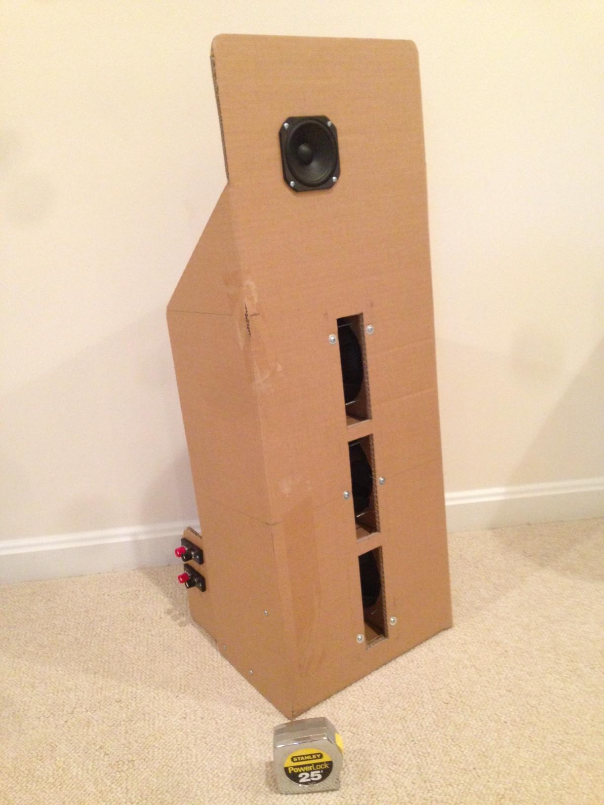
Thanks for showing us the details of this build. I never thought of the whole force cancellation at all but now that you mention it, my build with 6 drivers and with the very lightweight cardboard construction did not move from the cone movement either. The baffle did vibrate due to the sound pressure generated though so I like your idea of a constrained baffle. For folks in this forum not familiar with my cheap cardboard slot loaded OB, it can be found here: http://www.diyaudio.com/forums/full-range/249984-cheap-fast-ob-literally.html
It was very cool how we both arrived at very similar designs independently.
Your build is very nice and I may have to look into CNC construction as I use Solidworks and can make 3d models for fab easily enough.
Z,
Your build is very nice and I may have to look into CNC construction as I use Solidworks and can make 3d models for fab easily enough.
Let me know if you want the SolidWorks files to review. The routing was very reasonable. Of course you would need to change the design as the Aura drivers are no more, but there are a lot of good details regarding how the panels are rabbeted together, and how the tooling holes are used to align things.
Impressive, indeed. I'm glad it worked for you. Good bass is such an important thing. They look great, too.
I wonder if you tried mounting the woofers facing each other rather than this way. I know the theory and the conventional reason for doing it the way you did, but based on my experience one time with an enclosure design referred to, I believe, as "acoustic feedback", and published in an old (1975-ish) issue of Hi Fi News, Gramophone or Studio Sound, I would give it a listen if I were building something like this–not least because it would be so easy to try.
With my box, built in 1976, which involved nothing more than two very low fs 12" woofers mounted back to back on opposite sides of a sealed enclosure, I got the most non-resonant bass I had ever heard–exactly as the designer claimed, and backed up with an almost flat impedance curve right through what should have been the system resonance.
I sold them (they were built for a client) but for the next few months all other speakers I heard had very obvious resonances in the bass range.
What are what looks like recessed screw holes on the front baffle?
I am quite a fan of using as much automation in design as possible, though I tend towards using laser where possible myself as CNC routing (milling) at larger sizes tends to be pricier.
The downside is of course that Laser, at present, usually isn't available cheaply in 3D, whereas CNC routing you can get 2.5D routing for recesses and whatnot done quite easily.
Indeed the price premium of CNC is the only thing stopping me from suggesting to anyone who wants a flat pack kit shipped overseas "why ship the kit when you could have the design sent to someone local to make it for you?"
It is almost certain that my next boxes are going to be machine cut.
Thanks for contribution - love the look of the finished product and input on use of CNC.
Built the U, W and H frames and large sheet with wings using various 12" drivers. Never could get the deep tight bass I'm looking for. However previous experience with multiple small drivers in closed boxes tells me your approach with slotted ports is something I should pursue. (Thanks also to NP and Xrk)
With the Aura no longer available PE has this one in the buyout section
6-1/2" Poly Cone Woofer 4 Ohm | 299-609
Would you consider this a suitable candidate and if so what changes to the slot would be required, if any?
Impressive, indeed. I'm glad it worked for you. Good bass is such an important thing. They look great, too.
I wonder if you tried mounting the woofers facing each other rather than this way.
What are what looks like recessed screw holes on the front baffle?
I did not try the alternate mounting, but there is no reason not too. It makes the rear box easier to get off and on with less protruding. Which brings me to the answer to your second question: the front baffle is monolithic and the rear enclosure bolts on to create the U-frame. What you see from the front are "Hurricane nut" inserts. The screws come through the enclosure from the back.
'76 was a great year- that's when I started building speakers. Took off a few decades after 1980.
CNC vendor.
The CNC cutting cost was low because the setup was so simple: all from one sheet, cut from one side. The shipping, however was a very significant cost. I used Allrout CNC in MI. AllRout CNC Routing Service they take SolidWorks files direct and did all the CAM conversion. (I did lay out the parts in the flat sheet for them to use.) I can't say enough how pleased I was with the quality of the parts absolutely no sanding was required.
I am quite a fan of using as much automation in design as possible, though I tend towards using laser where possible myself as CNC routing (milling) at larger sizes tends to be pricier.
The CNC cutting cost was low because the setup was so simple: all from one sheet, cut from one side. The shipping, however was a very significant cost. I used Allrout CNC in MI. AllRout CNC Routing Service they take SolidWorks files direct and did all the CAM conversion. (I did lay out the parts in the flat sheet for them to use.) I can't say enough how pleased I was with the quality of the parts absolutely no sanding was required.
Thanks for contribution - love the look of the finished product and input on use of CNC.
Built the U, W and H frames and large sheet with wings using various 12" drivers. Never could get the deep tight bass I'm looking for. However previous experience with multiple small drivers in closed boxes tells me your approach with slotted ports is something I should pursue. (Thanks also to NP and Xrk)
With the Aura no longer available PE has this one in the buyout section
6-1/2" Poly Cone Woofer 4 Ohm | 299-609
Would you consider this a suitable candidate and if so what changes to the slot would be required, if any?
The buyout driver's Qts is high which means it will require less Eq but it probably won't sound as tight. The x-max is lower, 3.5mm vs 5mm. I expect that this won't have the same low distortion as the Aura drivers. But they are cheap so it's worth a try to make a prototype (perhaps make the slots in MDF/plywood and the box in cardboard?).
I would probably go with one of the steel frame Peerless 6" if I was to try and duplicate this again because they have great motors, a little more money but after you put in all the effort, I am always unhappy when I "cheap out". As I remember they can be had for about $25 each.
Last edited:
Z
Great advice on the drivers. I was hoping that with 8 high Qts drivers and less need for equalization would offset the x max/motor issue. As you say they're cheap enough to just give it a try.
Could I push you to comment on slot changes if any. Are the slot dimensions driver dependent and if so can you point to some formula?
Do you have a detailed drawing you would care to share with us.
Z
Could I push you to comment on slot changes if any. Are the slot dimensions driver dependent and if so can you point to some formula?
Do you have a detailed drawing you would care to share with us.
There was nothing special with respect to the slot design, I just worked to keep the overall slot dimensions short to the front of the baffle to raise the 1/4 wave resonance (which measures around ~450Hz) and made the rear radius to fit the driver. The slot width of 2" was selected to allow the push-pull mounting of the drivers. Take a look at the photo of the naked baffle/slot assembly.
My Visio sketches were mostly not dimensioned. I would be happy to post these and/or the SolidWorks files, but I won't have time for a few days.
How to make the constrained layer damped baffle.
I can't believe no one has asked about the specifics of the damping layer in the baffle. Here is how the baffle is put together:
The damping sheet is roofing "ice shield" commonly used here in the Northeast to stop water from backing up underneath shingles and leaking in the winter. It's made from a combination of slag, asphalt and binders with an aggressive pressure sensitive adhesive (PSA) on one side and a thin plastic "foil" on the other. It's heavy and just a little gooey- and completely dead. A roll big enough for all the hobby speakers you ever want to build costs $75.
I compared this ice shield side by side with 30# roofing felt in various constructions. (The roofing felt was recommended by Vance Dickenson in "The Loudspeaker Design Cookbook".) The ice shield definitely provides better damping and is easier to use overall. (Both of these materials don't like being routed after assembly- they make a gooey mess of a router bit and the workpiece.)
So, first you use spray adhesive to adhere the non (PSA) side of the ice shield to the front of the baffle and trim with a knife:
.jpg")
Then you remove the PSA backer:
.jpg")
Finally you use registration pins (drill bits) in the tooling holes to make sure the baffle is aligned during assembly and place the back of the baffle on the stack:
.jpg")
Apply pressure (photographer's foot):
.jpg")
Here you can see the sandwich up close:
.jpg")
.jpg")
Then glue together the woofer slot assembly (notice the registration pins again):
.jpg")
And glue the slot assembly to the rear baffle half:
.jpg")
To end up with the completed baffle:
.jpg")
As an added benefit, because of the sandwich construction, you end up with cut features (round-overs, bevels, counter-bores, etc.) on both sides of the baffle even though you only paid to have CNC cutting done on one side of a sheet. Not too shabby 😀.
I wish I could convey how a knuckle whack sounds like a "thud" instead of a "knock" when you strike the baffle, but it really works well. Between this solid, damped construction and the woofer force canceling, you can't feel any woofer vibrations in the panel. Baffle vibrations from the mid-range drivers are muted too.
I can't believe no one has asked about the specifics of the damping layer in the baffle. Here is how the baffle is put together:
The damping sheet is roofing "ice shield" commonly used here in the Northeast to stop water from backing up underneath shingles and leaking in the winter. It's made from a combination of slag, asphalt and binders with an aggressive pressure sensitive adhesive (PSA) on one side and a thin plastic "foil" on the other. It's heavy and just a little gooey- and completely dead. A roll big enough for all the hobby speakers you ever want to build costs $75.
I compared this ice shield side by side with 30# roofing felt in various constructions. (The roofing felt was recommended by Vance Dickenson in "The Loudspeaker Design Cookbook".) The ice shield definitely provides better damping and is easier to use overall. (Both of these materials don't like being routed after assembly- they make a gooey mess of a router bit and the workpiece.)
So, first you use spray adhesive to adhere the non (PSA) side of the ice shield to the front of the baffle and trim with a knife:
Then you remove the PSA backer:
Finally you use registration pins (drill bits) in the tooling holes to make sure the baffle is aligned during assembly and place the back of the baffle on the stack:
Apply pressure (photographer's foot):
Here you can see the sandwich up close:
Then glue together the woofer slot assembly (notice the registration pins again):
And glue the slot assembly to the rear baffle half:
To end up with the completed baffle:
As an added benefit, because of the sandwich construction, you end up with cut features (round-overs, bevels, counter-bores, etc.) on both sides of the baffle even though you only paid to have CNC cutting done on one side of a sheet. Not too shabby 😀.
I wish I could convey how a knuckle whack sounds like a "thud" instead of a "knock" when you strike the baffle, but it really works well. Between this solid, damped construction and the woofer force canceling, you can't feel any woofer vibrations in the panel. Baffle vibrations from the mid-range drivers are muted too.

Seriously impressive craftsmanship - and the acoustic design looks logical, too.
Kudos.
I think you've earned a
Kudos.
I think you've earned a
Very cool design, I bet the Auras sound quite good.
I was inspired by Linkwitz and the Nelson Pass slot loaded speakers as well. This is part of the my speaker, just the sub woofer section to test the slot width. The baffle will extend up for the bass, midrange and tweeter. One thing I can say is the Dayton RSS390 is a beast.
Rob
I was inspired by Linkwitz and the Nelson Pass slot loaded speakers as well. This is part of the my speaker, just the sub woofer section to test the slot width. The baffle will extend up for the bass, midrange and tweeter. One thing I can say is the Dayton RSS390 is a beast.
Rob
Attachments


Very cool design, I bet the Auras sound quite good.
I was inspired by Linkwitz and the Nelson Pass slot loaded speakers as well. This is part of the my speaker, just the sub woofer section to test the slot width. The baffle will extend up for the bass, midrange and tweeter. One thing I can say is the Dayton RSS390 is a beast.
Rob
Very nice- try not to knock over the guitars 😀.
You are going to have a 1/4 wave resonance at about 220Hz from the slot depth. Are you planning to use this sub above 100Hz?
Ice shield roofing material is a great tip. I will have to try it... maybe on cardboard 😀
Love the cardboard idea, so easy to do a test. The damping layer needs something with a high stiffness on either side to work, the first layer of paper in the corrugated board might be enough, but I don't know.
What would be stiff but soft enough to cut with a knife? A heavy Aluminum foil? Any other ideas?
Very nice- try not to knock over the guitars 😀.
You are going to have a 1/4 wave resonance at about 220Hz from the slot depth. Are you planning to use this sub above 100Hz?
Fortunately the guitars are safe, the enclosure was just setup there for initial testing 😉. The sub will only be used up to ~75Hz. 220Hz is a good guess, the resonance is at 194Hz:
Attachments

Last edited:
Fortunately the guitars are safe, the enclosure was just setup there for initial testing 😉. The sub will only be used up to ~75Hz. 220Hz is a good guess, the resonance is at 194Hz:
Great work on the build, very solid. Love to see more on the speaker as you progress.
- Status
- Not open for further replies.
- Home
- Loudspeakers
- Multi-Way
- Novel Open Baffle Construction Techniques