View attachment 404714
MF-HF Directivity
I will let the data speak for itself, but everyone who has heard them has been impressed with the rock solid imaging and tonal balance. I was slightly disappointed with a "shoulder" in the directivity plot around 1.3kHz, but overall it's very good. Response is +/-2dB from 35-20kHz on axis except for a 3.5dB dip around 1.3kHz that's on purpose. The true standout though, is the bass; the directivity is an almost perfect dipole as the outdoor measurements below show (un-gated, 2m ground bounce). A double bass, cello or a kick drum sounds like it's in the room, really. The speakers don't get at all muddy if you want to listen to Slipknot (which I don't). Toms hit you in the chest. You can feel no bass vibration in the baffle, the woofer force-canceling really works. Mid frequency vibration in the baffle is very low, the damping layer works.
Hi Z, this is a really well executed project. I like the way you cut the side holes of the mid/tweeter to enhance directivity. Been thinking about this for quite sometimes for my own speakers but I can't bear thinking of ruining my mahogany baffle in case I make mistakes, which I do often

Like you I have been thinking to just CNC my next speakers. Enough MDF dust !!!.... 'Luckily' I haven't build anything new since.....
What was the the thought before about slot loaded open baffle? They clearly look dipole to me?
Nelson Pass claimed in a report he published that a slot loaded woofer had up to 9bB of gain because of the high velocity of the air in the slot. Here's that report: The Slot Loaded Open Baffle Project Article By Nelson Pass
This claim appeared to bother JohnK, because it was only a near-field effect. He protested it was misleading and "there was too much fuss about it" on a PE tech talk forum post: From Nelson Pass: Slot Loaded Open Baffle Project
I also found a very well done technical manuscript by John on the topic where he showed that the only "real" gain was from slot resonance, but I can't find that anymore. Perhaps John can share it.
In my case, the slot configuration was used because my previous dipole with 12 of the Aura drivers had a lot of "bulk" movement of the speaker from the bass. The slot configuration promised to cancel the forces and eliminate this- It worked great for that in this design. My slot ratio was also quite small; I think around 2x driver diaphragm area to slot area, so the front velocity is not increased as much. That's probably why at even only 2m it measures so much like a dipole.
Hi Z, glad you got time to do a write up about your slot loaded open baffle build. Loads of useful info to digest and new areas to explore.
On the subject of constrained layer dampening. You wrote 'Ice Shield', would this be Grace Ice & Water Shield? Not a brand easily available here in the UK, though chanced upon this from IKO.
Paul
On the subject of constrained layer dampening. You wrote 'Ice Shield', would this be Grace Ice & Water Shield? Not a brand easily available here in the UK, though chanced upon this from IKO.
Paul
Here is the link to my discussion of the slot loaded woofer.
Nelson Pass Slot loaded OB
Also I think a lot of people don't understand the behavior of a dipole source as you move closer to it.
http://musicanddesign.com/Dipole-axis.html
which is why near field measurements make it look like there is some additional gain, slot loaded or otherwise.
Nelson Pass Slot loaded OB
Also I think a lot of people don't understand the behavior of a dipole source as you move closer to it.
http://musicanddesign.com/Dipole-axis.html
which is why near field measurements make it look like there is some additional gain, slot loaded or otherwise.
Last edited:
Constrained Layer Materials
Paul,
Here is a photo of all of the consumables I used for the project including the ice shield which is a GAF product: "StormGuard" GAF | StormGuard Water & Ice Shield. (In the MSDS datasheet you'll find the composition.) The IKO product is about twice as thick, I think a little too thick.

Consumable Materials
Wish they made this stuff with the PSA on both sides, then things would be real easy. The "top" gray side has a very thin layer of what I assume is polyethylene or some similar low surface energy material. Despite it being micro textured (so the roofers don't slip on it) I still assumed it would be hard to bond. So, I used the super aggressive 3M #90 spray adhesive, coating the StormGuard and the MDF before bonding and then pressed it on good with a rolling pin (don't tell my wife).
A word of caution. Don't press a panel together and then try to cut or route it. It works, but it makes a gooey black tar-like mess of the tools and the edge. Here's an example of a 3-layer (Baltic-birch/MDF/Baltic-birch) panel from another project I routed after making the sandwich, ugly.

Don't Route after Assembly!
It has nothing to do with the CLD layer, but the photo above shows everything else that was used to build the cabinets- just wood glue and clear shellac. The shellac was applied by an HVLP gun that was bought at Harbor Freight. I normally hate everything in Harbor Freight, usually just plain crap IMHO. But several posts on woodworking forums said the $20 gun was excellent and they were right. Even though I made the newbie mistake of not cutting the shellac, the finish came out great. It dries so fast you can put another coat on one speaker while the other one dries... Ad infinitum. The only other tools used for assembly were a knife, a screwdriver and wood clamps (and shhhhh, the rolling pin). I really did not use sandpaper- The power of CNC!

Economical and Excellent Spray Gun
I was intending that the shellac was just going to be to sealing coat, but it really looks great. Next project I am going to try dieing the shellac- red/black to give the MDF a dark crimson color. It would be less forgiving to apply than clear, but it would look cool.
Glad everyone is so appreciative of the info. I have to go in to work to get them, but tomorrow I hope to post the SolidWorks files.
Paul, If you want to have a sample of the ice shield so you can compare to local UK products, PM me your physical address and I'll mail you a scrap.
Hi Z,
...On the subject of constrained layer dampening. You wrote 'Ice Shield', would this be Grace Ice & Water Shield? Not a brand easily available here in the UK, though chanced upon this from IKO.
Paul
Paul,
Here is a photo of all of the consumables I used for the project including the ice shield which is a GAF product: "StormGuard" GAF | StormGuard Water & Ice Shield. (In the MSDS datasheet you'll find the composition.) The IKO product is about twice as thick, I think a little too thick.
Consumable Materials
Wish they made this stuff with the PSA on both sides, then things would be real easy. The "top" gray side has a very thin layer of what I assume is polyethylene or some similar low surface energy material. Despite it being micro textured (so the roofers don't slip on it) I still assumed it would be hard to bond. So, I used the super aggressive 3M #90 spray adhesive, coating the StormGuard and the MDF before bonding and then pressed it on good with a rolling pin (don't tell my wife).
A word of caution. Don't press a panel together and then try to cut or route it. It works, but it makes a gooey black tar-like mess of the tools and the edge. Here's an example of a 3-layer (Baltic-birch/MDF/Baltic-birch) panel from another project I routed after making the sandwich, ugly.
Don't Route after Assembly!
It has nothing to do with the CLD layer, but the photo above shows everything else that was used to build the cabinets- just wood glue and clear shellac. The shellac was applied by an HVLP gun that was bought at Harbor Freight. I normally hate everything in Harbor Freight, usually just plain crap IMHO. But several posts on woodworking forums said the $20 gun was excellent and they were right. Even though I made the newbie mistake of not cutting the shellac, the finish came out great. It dries so fast you can put another coat on one speaker while the other one dries... Ad infinitum. The only other tools used for assembly were a knife, a screwdriver and wood clamps (and shhhhh, the rolling pin). I really did not use sandpaper- The power of CNC!
Economical and Excellent Spray Gun
I was intending that the shellac was just going to be to sealing coat, but it really looks great. Next project I am going to try dieing the shellac- red/black to give the MDF a dark crimson color. It would be less forgiving to apply than clear, but it would look cool.
Glad everyone is so appreciative of the info. I have to go in to work to get them, but tomorrow I hope to post the SolidWorks files.
Paul, If you want to have a sample of the ice shield so you can compare to local UK products, PM me your physical address and I'll mail you a scrap.
Last edited:
Thanks Z, great info once again.
Should be ok with just the datasheet for the GAF Ice & Water Shield... looked at a few different makes of roofing underlayment here, most didn't look heavy enough. Think the IKO one linked won't be to far off.
Quite familiar with Titebond glue and 3M spray adhesives, I use 'Photo Mount' fairly regular... I have done airbrush work for a few years. Unfortunately, I don't think my compressor & tank is of a high enough flow rate or capacity to make using a larger spray gun an easy task. Will have to take another look as spraying is lots more fun than brushing the stuff on.
For dies, have a look at the ColorTone range. The liquid stains can be cut with water or alcohol, so might be usable with cut shellac.
Seen a thread here about a modular OB design where the Eminence Alpha 15A and FR drivers are mounted on separate square cut baffles, then mounted on a metal sub frame. I liked the way the squares helped break up the vertical lines and wondered about doing something similar, but mounting the front baffle onto an MDF panel with the membrane between...
CNC is the way forward, it's just getting the work done for the right price. I'll stick with the hand tools while my builds are still fairly simple
Thanks Z, great info once again.
For dies, have a look at the ColorTone range. The liquid stains can be cut with water or alcohol, so might be usable with cut shellac.
Paul,
Thanks for the tip on the dies, I'll see if I can get them on this side of the pond.
Those ColorTones are an American make so you should be ok
Had a look at HVLP spray guns, there's some nice one's available through Amazon at attractive prices. Plus found a new 24L 1.5HP 6.35cfm air compressor for £65 inc. P&P
Need to make my mind up now, try out a straight forward OB build first, or jump straight into the deep end and try building a slot loaded OB... choices
Need to make my mind up now, try out a straight forward OB build first, or jump straight into the deep end and try building a slot loaded OB... choices
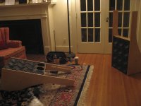
Dangerous. The photos below show a bit of my OB project from the summer of '12. This one too started in my head as just a board with some holes in it. I called it the "Colossal"; my wife called me a fool.
After a whole summer of hand woodwork and finishing I measured it and it was good but not great. So I have them now with all the drivers installed, and the passive x-over for the upper panel designed, but I suddenly could no longer bear to work on them.
Hmmm... I have just acquired a DEQx crossover and I have an 8 channel amp, I should just hook them up and let it calibrate them...
See, the affliction continues.
My only point is- make sure your ambition does not exceed your patience. Make something quick and give it a listen. The CNC cutting enabled that for me. For others it's foam core, or living with an ugly prototype, etc.
Attachments
Enclosed: 3D SolidWorks Files
Enclosed are the SolidWorks files for all of the speaker components and also an assembly of the entire speaker.
.jpg")
The files enclosed fit together perfect, but would have added a few features if I did it again:
Since the Aura drivers are unavailable now I doubt any of you will build them, but the files show all of the details regarding the features for ease-of-assembly.
Z,
Your build is very nice and I may have to look into CNC construction as I use Solidworks and can make 3d models for fab easily enough.
Enclosed are the SolidWorks files for all of the speaker components and also an assembly of the entire speaker.
The files enclosed fit together perfect, but would have added a few features if I did it again:
- Added parts for the rear tweeter mount (even though I have never used the tweeter)
- Integrated groves into one of the slot spacers for wires from the inverted woofers.
- Cut the rear grill supports (I used 1x1 stock), made a rabbet for them to fit into in each of the sides and made holes for inserts.
- Put a logo on the front (since I never covered the baffle with fabric)
Since the Aura drivers are unavailable now I doubt any of you will build them, but the files show all of the details regarding the features for ease-of-assembly.
Attachments
Last edited:
Z,
That is very kind of you to provide the SW files! Anyone can build this - now if we can only get those Aurasound 6 in woofers that sold out last year! I can mod it to accommodate the 6.5 in PE Buyout polycone woofers that I currently use on my slot OB.
Thanks,
X
Edit: I just tried opening the files on my SW 2009 and it said future version - cannot open. Would you mind saving your files as an older version (2009) and re-posting? - Thanks.
Last edited:
2009 Files
X,
It'll take me a couple of days- I have to ask an ME to do that for me.
Interested to see the modified design when it's done. It would be good to have it work with a woofer that will be around a while as well as the buyouts. This is a solid performer:
Peerless SDS-160F25PR01-08 6-1/2" Paper Cone Woofer Speaker | 264-1146.
Do you use SolidWorks daily in your job?
Z
Z,
Edit: I just tried opening the files on my SW 2009 and it said future version - cannot open. Would you mind saving your files as an older version (2009) and re-posting? - Thanks.
X,
It'll take me a couple of days- I have to ask an ME to do that for me.
Interested to see the modified design when it's done. It would be good to have it work with a woofer that will be around a while as well as the buyouts. This is a solid performer:
Peerless SDS-160F25PR01-08 6-1/2" Paper Cone Woofer Speaker | 264-1146.
Do you use SolidWorks daily in your job?
Z
Z,
I hear you about designing stuff to buyout drivers - there is no longevity to the design. Maybe should go with the Peerless you suggest but I love cheap drivers that sound good.
I use SolidWorks maybe a few times a month now - when I have to go back to look at some of the projects I used to work on to get data.
Thanks for getting the older format files from your friend.
X
Last edited:
Z,
I hear you about designing stuff to buyout drivers - there is no longevity to the design. Maybe should go with the Peerless you suggest but I love cheap drivers that sound good.
I use SolidWorks maybe a few times a month now - when I have to go back to look at some of the projects I used to work on to get data.
Thanks for getting the older format files from your friend.
X
The dimensions may be similar enough that it could work for the buyouts and a stock woofer; could be the same slot design with a second set of pilot holes for mounting.
3D files, Redux

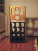
Speaker Assy. from Front
SolidWorks in their infinite wisdom dropped the "save in old version" feature from SW13 so I can't provide SW9 files. Everyone want's to upgrade, right? Don't get me going...
What I have enclosed are STEP files that should import directly into SW9 or any other 3D drafting program.

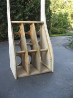
Slot Assy. Before Gluing to Baffle
Z,
Edit: I just tried opening the files on my SW 2009 and it said future version - cannot open. Would you mind saving your files as an older version (2009) and re-posting? - Thanks.
Speaker Assy. from Front
SolidWorks in their infinite wisdom dropped the "save in old version" feature from SW13 so I can't provide SW9 files. Everyone want's to upgrade, right? Don't get me going...
What I have enclosed are STEP files that should import directly into SW9 or any other 3D drafting program.
Slot Assy. Before Gluing to Baffle
Attachments
Nice work Z!
Your approach to the Pass variation is very intriguing. A system of four 10" woofers would be a nice alternative with equal surface area yet still avoiding the slot resonance if crossing below 250hz.
In another thread, a similiar 'leaky' enclosure was proposed with slotted sides of varying depth filled with open cell foam which potentially could lower extension by forcing dipole cancellations lower in frequency. The trick is not to load the back wave of the drivers where the system efficiency is effected and the gains of the slot design are nullified. Quite a balancing act.....but feasible with the right drivers.
Nice work Z!
Your approach to the Pass variation is very intriguing. A system of four 10" woofers would be a nice alternative with equal surface area yet still avoiding the slot resonance if crossing below 250hz.
In another thread, a similiar 'leaky' enclosure was proposed with slotted sides of varying depth filled with open cell foam which potentially could lower extension by forcing dipole cancellations lower in frequency. The trick is not to load the back wave of the drivers where the system efficiency is effected and the gains of the slot design are nullified. Quite a balancing act.....but feasible with the right drivers.
A system with the 10's could make the speaker shorter, but probably wider overall. Based upon the response I found near resonance, I would not cross a deep slot like that above 100Hz which the mids I used would not handle. But going to an 8" mid and then a small cone mid-tweet could work well. A million variations are possible.
The vented (slotted) side enclosures usually yield a cardoid pattern, which could be good if it's uniform with frequency. It's a very empirical exercise to get that sort of thing right. Many iterations- too many for my patience.
Quite an exercise! One benefit of the Cardoid pattern is the ability for dipoles to be placed closer to boundaries.......opens them up to many who may not be able to place the speakers where current dipole systems suggest.
After reviewing the entire Pass thread, I can't see any reason why I should expect a resonance anywhere below 250hz, and if I'm carefull with choosing the slope the resonant peak might be an advantage given the typical in room null found in that area.
After reviewing the entire Pass thread, I can't see any reason why I should expect a resonance anywhere below 250hz, and if I'm carefull with choosing the slope the resonant peak might be an advantage given the typical in room null found in that area.
- Status
- This old topic is closed. If you want to reopen this topic, contact a moderator using the "Report Post" button.
- Home
- Loudspeakers
- Multi-Way
- Novel Open Baffle Construction Techniques