Link to measurement of the tweeter on axis at 50cm from the driver in box without filter
http://www.diyaudio.com/forums/multi-way/236392-help-3-4-way-loudspeaker-37.html#post3852282
http://www.diyaudio.com/forums/multi-way/236392-help-3-4-way-loudspeaker-37.html#post3852282
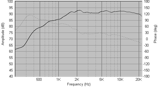
I think you should refine your measurements. This is what I have with a different tweeter (Seas 27TBF/C), without crossover but mounted on the box:
http://www.diyaudio.com/forums/attachments/multi-way/350675d1369488525-another-6-5-1-br-design-peerless-hds-seas-prestige-s27tbfcg-baffle.jpg
Anyway, the excel tweeter (with ferrofluid) should behave not too differently, and a 2nd order electrical network at 2.5KHz should be enough to shape the response. I wouldn't use a LCR notch to tame the (non existent) resonance bump.
Ralf
Zobel is to flatten the impedance after the resonant peak.If you only need to flatten the impedance on a tweeter after the resonance then you need a Zobel.
IMHO, if you learn to use a proper crossover software (Speaker Workshop or Passive Crossover Designer), you'll realize that Zobels aren't necessary.
A notch needed to eliminate a bump is quite impossible to do right without measurements.
Troels Gravesen uses LCR notches on woofers mainly to eliminate the bump in the midrange (500Hz-1Kz) due to the baffle step effect. I think it is explained on one of the recent designs (Seas Curv perhaps).
Ralf
Notch filter is to reduce the impedance at the notch frequency which is chosen to coincide with a peak in frequency response that needs attenuating.
The added resistor determines the depth of the notch to suit how big the peak is.
my profile.Andrew what do you do?
Zobel is to flatten the impedance after the resonant peak.
Notch filter is to reduce the impedance at the notch frequency which is chosen to coincide with a peak in frequency response that needs attenuating.
The added resistor determines the depth of the notch to suit how big the peak is.
Andrew what do you do?
What is the question to which Merlin asks: "what would I do if I had to make a decision?"andrew t
i think he meant "Andrew what would you do?"
andrew t
i think he meant "Andrew what would you do?"
Thanks
What is the question to which Merlin asks: "what would I do if I had to make a decision?"
Yes
A pasive filter will only be as good as the model predicts IF YOU ensure that what you tell the model is correct.
A single pole RC high pass filter using C in series with a constant fixed resistance will roll off at the predicted frequency and will slope down at the predicted 6dB/octave until the R or the C parasitics begin to take over and eventually dominate the filters response.
If you feed a speaker which has an effective inductance in the voice coil, you will NEVER predict the filter response with an RC filter.
The R part has ignored the speaker inductance.
You can make a better model by adding a correctly calculated Speaker Zobel to the driver to mimic a near resistive loading on the filter.
Now your model does give quite a good correlation to the real filter.
I would never try to design a passive speaker filter using a bad model.
But there again I have never designed a multiway speaker.
I have built a few from proved working designs.
I have designed a few active low bass speakers, but that is very different.
Jeff Bagby's Passive Crossover Designer or PCD is a proven tool for passive xovers - as long as you enter good data taken by measuring SPL and impedance of the drivers in the cabinets you plan to use and generate .frd and .zma files to use with PCD.
Jeff Bagby's Software Page
Jeff Bagby's Software Page
merlin be careful if you don't use proper english spelling and punctuation you risk being chastised for it. you may have to ask:"Andrew forget the calculator, what would you do?"
and considering Andrew's knowledge base on audio his answer would be valuable!
turk 182, English isn't my native language, I guess Andrew knows if not I apologize in advance.
turk 182, ingles no es mi lengua nativa, supongo que Andrew lo sabe en caso contrario le pido disculpas por anticipado.
- Status
- This old topic is closed. If you want to reopen this topic, contact a moderator using the "Report Post" button.
- Home
- Loudspeakers
- Multi-Way
- How to calculate series notch filters