... and it works brilliantly! Thanks again Jean-Michel.
Kind regards,
David
Hello David,
Thanks for the kind words.
As you provide a spectrogram of the calculated Impulse Response. I must add that the Spectrogram itself does not use any FFT (1 : FFT is not so convenient when using a log frequency scale; 2 : FFT is not so fast as the algorithm I wrote for the Spectrogram module in Hornresp).
To reduce computing time, the algorithm I wrote for the Spectrogram is also using a bell shape window without any more complex functions used than sums, multiplication and division...). This window is not a raised cosine but it approximate a Gaussian window. (A gaussian function can be very easily approximated using very few iteration of a box filter).
See
Gaussian approximation using box filter | Nghia Ho
Best regards from Paris, France
Jean-Michel Le Cléac'h
Markus, it is obviously the region that needs the most attention once everything above it has been attended to. Carefully removing the baffle transition region is one way to do this and can make a considerable improvement. Some are suggesting that it isn't necessary and I guess I have to assume they know more than I do, as I have never been able to make a normal baffled speaker sound the same.
While polar’s in room are “problematic” one can get an idea how well a speaker will interface with a boundary by going outside and measuring two identical loudspeakers.
This would be using another loudspeaker for the “mirror image” one would have with a physical boundary in the same location.
For a loudspeaker to be array able acoustically (compatible with an identical source or physical boundary) it cannot interfere significantly with the adjacent speaker.
When that is the case, one can also place it on a boundary in the same geometry with a similar (absence of audible change) result.
If one isn’t able to make a polar plot, playing music or better yet pink noise through both will make interference very audible as you move from the coverage of one to the other. In fact, pink noise and moving around is a fair audible test for a single speaker as well to indicate self interference.
Ideally (and it is rare but still possible) to have NO audible seam or comb filtering / swishyness as you move back and forth.
Fwiw, I can’t say that I have ever seen / measured a loudspeaker that had cancellation notches alone, that went away when on a boundary or with an adjacent source.
Best,
Tom
With the radial array:
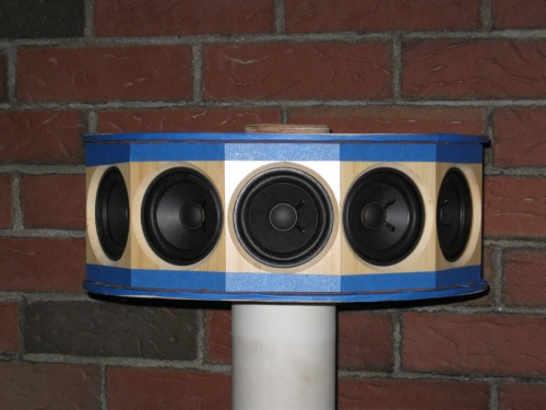
their is virtually no "swishyness" with noise signal while moving from in front of one speaker to the other. Noise blob maintains spectral character and pans smoothly from one speaker to the other speaker as head moves from in front of speaker to in front of other speaker. This remains largely unchanged even with arrays placed directly in front of wall. Standing in front of speaker, it blocks its own reflection, so initially a small shift in spectral balance is perceived as head starts transit to other speaker. Likewise, motion along center line between speakers, from virtually standing in between speakers and on outwards, perception of virtual sound blob has no "swishyness"/spectral change.
...........
By the way, how's your wide dispersion speaker coming along?
Markus;
Thanks for asking. While in the previously pictured state, I beat on in pretty hard, and not surprisingly a few drivers opted for early retirement. Having established some sense of limits, woofers were added:

A pair of Peerless 10" SLS. These operate 80-300Hz. <80Hz, stereo signal is summed and sent to single 12" sealed sub.
The setup puts a full circle spin on "Uniform Directivity", and tips on ear certain notions about perception of diffraction and of comb filtering.
Horizontal response: With 12 drivers, the pattern repeats over 30 degree intervals, further symmetry over any drivers axis means entire response in horizontal plane is seen across 15 degree span.
Here are measurements of radial array across 30 degrees in 2.5 degree intervals. Measurements taken at 21 inches, with microphone fixed and speaker rotated for each measurement. Windowing captures 6ms past impuse peak using Blackman-Harris 7 term filtering. Results are smoothed with 1/24 octave window:

And for what it's worth, REW's averaged response of the above:

I believe the most important region is the frequency range where your speakers are no longer CD. The room filter creates ambiguous cues for stereo reproduction.
We've been here before as well - we don't agree.
^
You don't agree that your speakers are no longer CD in that region or that the room creates ambiguous localization cues (which also happens with speakers that have high directivity at low frequencies)?
You don't agree that your speakers are no longer CD in that region or that the room creates ambiguous localization cues (which also happens with speakers that have high directivity at low frequencies)?
You two sound like an old married couple 😛
More like "master" and disillusioned "disciple". 😀
Both make good points.
But only one has an over-riding bias. 😉
This question, from another DIYaudio thread, seemed more appropriate here:
I lifted the equations used to describe the H290C waveguide/horn from a document describing the device:

That shows in some detail the flare profile I used. What is not shown by those formulas are the mouth radius and the profile at the edges.
The mouth radius is borrowed from LeCleach, in that it is a gradually increasing angle calculated using an iterative approach. But it is not a large part of the total profile so in truth, it could have been a tractrix or some other shape, even an arbitrary radius. I just wanted to avoid any sharp edges.
Similarly, I wanted to provide smooth features on the diagonals, but also to maintain as much of the area as possible, which is why I chose a rectangular profile. I think the super-ellipse would have been fine too, but I saw no reason to take that shape, so what I did was to use the same formula as shown above and apply it for the oblique angles, but just enough to provide a round entrance that gradually blends the sides with top and bottom so that the exit is rectangular.
The end result is a shape that has slightly wider tangential angles on the diagonals. The profile starts off round, then slowly changes to elliptical, then towards more of a super-ellipse, then finally to a rectangular exit. But the profile at every point - horizontal, vertical or obliques - is described by the trigonometric formula above.
My design goals were to create a device that had uniform directivity but not at the expense of response smoothness. I also wanted an asymmetrical flare, because I like the ability to minimize the vertical spacing of MF and HF sound sources.
I always thought that discontinuities inside the horn caused response ripple due to impedance spikes. They also cause diffraction, which may be useful for widening the pattern but it destroys imaging. So waveguides are attractive in that they limit these problems, but many of them aren't so good at acoustic loading, and so suffer from response ripple. I wanted the best of both worlds, and I found that it is possible, provided you design the waveguide paying attention not only to flare profile but also area expansion and length.
I think the biggest difference between the H290C waveguide/horn and other similar designs is mostly what I said in that last sentence. I designed for both smooth wavefront propogation and smooth response. I think the effort was worth it, and this attention to detail pays off in a smoother sounding device, one that shows in measurements. You can clearly see the benefits of improved response from the H290C, as compared with another similar waveguide, in the first post of this thread.
How similar is the cross section of the 290C in comparison to the TH-4003 shown in the link?
https://www.google.com/search?q=th4...26start%3D8550%26sort%3D1%26number%3D;496;701
I lifted the equations used to describe the H290C waveguide/horn from a document describing the device:
That shows in some detail the flare profile I used. What is not shown by those formulas are the mouth radius and the profile at the edges.
The mouth radius is borrowed from LeCleach, in that it is a gradually increasing angle calculated using an iterative approach. But it is not a large part of the total profile so in truth, it could have been a tractrix or some other shape, even an arbitrary radius. I just wanted to avoid any sharp edges.
Similarly, I wanted to provide smooth features on the diagonals, but also to maintain as much of the area as possible, which is why I chose a rectangular profile. I think the super-ellipse would have been fine too, but I saw no reason to take that shape, so what I did was to use the same formula as shown above and apply it for the oblique angles, but just enough to provide a round entrance that gradually blends the sides with top and bottom so that the exit is rectangular.
The end result is a shape that has slightly wider tangential angles on the diagonals. The profile starts off round, then slowly changes to elliptical, then towards more of a super-ellipse, then finally to a rectangular exit. But the profile at every point - horizontal, vertical or obliques - is described by the trigonometric formula above.
My design goals were to create a device that had uniform directivity but not at the expense of response smoothness. I also wanted an asymmetrical flare, because I like the ability to minimize the vertical spacing of MF and HF sound sources.
I always thought that discontinuities inside the horn caused response ripple due to impedance spikes. They also cause diffraction, which may be useful for widening the pattern but it destroys imaging. So waveguides are attractive in that they limit these problems, but many of them aren't so good at acoustic loading, and so suffer from response ripple. I wanted the best of both worlds, and I found that it is possible, provided you design the waveguide paying attention not only to flare profile but also area expansion and length.
I think the biggest difference between the H290C waveguide/horn and other similar designs is mostly what I said in that last sentence. I designed for both smooth wavefront propogation and smooth response. I think the effort was worth it, and this attention to detail pays off in a smoother sounding device, one that shows in measurements. You can clearly see the benefits of improved response from the H290C, as compared with another similar waveguide, in the first post of this thread.
Last edited:
I don't understand why the Le Cléac’h horns have become so popular. Can someone explain?
The response is not by any means uniform and they don't limit vertical reflections. Round horns seem to be the worse choice. You never see them in the pro/studio arena.
The response is not by any means uniform and they don't limit vertical reflections. Round horns seem to be the worse choice. You never see them in the pro/studio arena.
Round horns seem to be the worse choice. You never see them in the pro/studio arena.
This is an old discussion and isn't true. Pro/studio usage is no statement on performance. I've studied the problem in some detail and my conclusions are the opposite.
I have to say I put far more trust in the studio guys then audiophiles. But that's another discussion.This is an old discussion and isn't true. Pro/studio usage is no statement on performance. I've studied the problem in some detail and my conclusions are the opposite.
Either way, I can't comment on round horns in general but the polars of the Le Cléac’h horns (which I had in mind) are anything but impressive to me. Can't see why they should be so popular.
You apparently don't give me much credit.
I do agree with you about the Le Cleach horns, but their problems are not because they are round. They are popular because they look good. People somehow think that things that look good should sound good.
I do agree with you about the Le Cleach horns, but their problems are not because they are round. They are popular because they look good. People somehow think that things that look good should sound good.
I wasn't addressing you. I sure give you credit for both your speakers and studies/articles. I'm not exactly aware of your studies on this subject however.
To me they look like a donut on a stick. In other words; really stupid. That's my taste though.
To me they look like a donut on a stick. In other words; really stupid. That's my taste though.
I've never liked 90° round horns, myself. I like waveguide/horns, I like having approximately 90° horizontal beamwidth and I like uniform directivity. But I do not like round horns for various reasons, which I've mentioned scattered through this thread.
Of course, round horns have the same pattern in all directions. Rectangular and elliptical horns do not. Where the dimension is smaller, the pattern control will be lost first. Some call this pattern flip, but it's really not that simple. It's directivity that changes at a different point in each dimension, and at a different rate. But in the trade-off, one gains the ability to have less vertical distance between sound sources, and this provides a taller forward lobe. It also allows for a smaller area expansion, which can make smoother response in some cases. So these are worthwhile traits, in my opinion.
Of course, vertical spacing is not the only factor that sets the distance between vertical nulls. It is also a function of crossover frequency. However, if two horns are compared, both having the same horizontal dimension and flare profile, then they will have approximately the same horizontal directivity. Therefore, if the goal is to match directivity in the horizontal plane between a direct radiating midwoofer and the tweeter horn, then crossover will be the same frequency whether the horn is round or elliptical/rectangular. The only difference is in the response along movement in the vertical dimension. The loudspeaker system with closer vertical spacing will have a taller clean forward lobe through the crossover region, with the vertical nulls and secondary lobes spaced further apart.
- Measurement of vertical nulls (video)
Again, Wayne oversimplifies the problem.
Yes, if the two waveguides have the same horizontal dimension then they should have the same crossover frequency. The circular one has the same directivity vertical as it does horizontal and so the vertical lobe is predictable and if this crossover frequency is low enough then the main forward lobe is wide enough to not be an issue. If the waveguide is elliptical then the vertical directivity is loosing control much earlier than the horizontal and will NOT match the woofer at the crossover and the vertical lobe will not be as well controlled as it is with the circular waveguide. There may be specific aspect ratios of the elliptical that are better or worse, but in general one can never say that all elliptical waveguides will have a wider vertical lobe than all circular ones. It is simply not that trivial a problem. In the cases that I looked at there was very little difference between the elliptical and the circular. Certainly not enough to justify the large complication in manufacturing the elliptical one. Square ones are even worse than elliptical because across the diagonal is far worse than the vertical - quite often a complete disaster. That's my take on the subject - based, of course, on data and NOT on some subjective impressions or hand waving arguments.
Yes, if the two waveguides have the same horizontal dimension then they should have the same crossover frequency. The circular one has the same directivity vertical as it does horizontal and so the vertical lobe is predictable and if this crossover frequency is low enough then the main forward lobe is wide enough to not be an issue. If the waveguide is elliptical then the vertical directivity is loosing control much earlier than the horizontal and will NOT match the woofer at the crossover and the vertical lobe will not be as well controlled as it is with the circular waveguide. There may be specific aspect ratios of the elliptical that are better or worse, but in general one can never say that all elliptical waveguides will have a wider vertical lobe than all circular ones. It is simply not that trivial a problem. In the cases that I looked at there was very little difference between the elliptical and the circular. Certainly not enough to justify the large complication in manufacturing the elliptical one. Square ones are even worse than elliptical because across the diagonal is far worse than the vertical - quite often a complete disaster. That's my take on the subject - based, of course, on data and NOT on some subjective impressions or hand waving arguments.
There may be specific aspect ratios of the elliptical that are better or worse, but in general one can never say that all elliptical waveguides will have a wider vertical lobe than all circular ones. It is simply not that trivial a problem. In the cases that I looked at there was very little difference between the elliptical and the circular.
See, but there's the rub. You actually can say with certainty that the rectangular or elliptical waveguide will have a larger vertical lobe because vertical spacing is smaller. I mean, if you spread the woofer and tweeter apart that wouldn't be the case but if you take advantage of the reduced waveguide height and mount them closer together, it most certainly is.
I would be right there with you on the round waveguide/horns if that weren't the case.
You are assuming that the vertical directivity is the same between the two situations, but it is not. The directivity narrows on the elliptical due to the smaller mouth dimension, but somehow you want me to believe that this will make the main lobe wider. 😕 Not quite true. Best case, and this is what I found, the closer spacing advantage is canceled by the narrower directivity disadvantage. No real net gain, just a good story, if you tell it right and ignore a few of the details.
That's not true, I do not assume anything. I am basing my comments on actual measurements. It is almost trivial to measure the verticals, and they act very predictably. Where the vertical spacing is closer, the forward lobe is taller with the nulls spaced further apart.
Yes, no real net gain, both systems still suffer from apparent sources separated by >1/4 wavelength of crossover frequency. Reflections from off axis have different ripple patterns that are dependent both on direction and distance traveled. Ignore this and directivity of both your systems is just fine.
Well, that's exactly right. The whole thing is about path length differences, and where they exceed the point where the sound sources sum constructively. Beyond that point, the sound sources begin to combine destructively, forming nulls. So naturally, it's important to keep the vertical spacing close enough the nulls are separated by a useful distance.
I can live with destructive interference outside about a +/-20° arc in the vertical. I tend to design loudspeakers that keep the nulls a little outside that, actually, around +/-25°. That provides a nice tall, clean forward lobe and waveguide speakers made that way measure and sound great.
But I've seen some well-regarded waveguide speakers with round horns that have vertical nulls less than 10° from the forward centerline. That's way too close, in my opinion. It's so close to the zero axis that the nulls are directly in front of the loudspeaker baffle all the way out 10 feet away from the speaker. That's a disaster, having a 10dB notch straight in front of the speaker. Talk about Emperor's New Clothes.
To tell the truth, if the vertical spacing between woofer and tweeter is too great, almost nothing else matters in the crossover region because destructive interference will dominate the response. You can talk all day long about other more subtle acoustic features but where there is destructive interference, the response takes a huge hit. So this is a very important part of the overall loudspeaker system design.
- Status
- Not open for further replies.
- Home
- Loudspeakers
- Multi-Way
- Uniform Directivity - How important is it?