So, now please explain me how this made up information aka 'good approximation' saves the Tooles example?
Maybe if I knew what that was I could answer the question...
OK, I only hope nothing dramatic will happen if I scan that page and post it here for others as well. Tomorrow..
Yes, you might get a call from the copyright infringement office. Do not post. It will probably be deleted by the mods here, who are sensitive to that kind of thing.
Instead you might offer that people contact you by PM and then you can send them a pdf copy to their Email address (for instance). I think you are allowed to do this, as long as you do not post it to the web.
For any finite time interval, DFT transforms time domain to frequency domain. No information is changed. Second application of DFT to this frequency domain returns original time domain.
Impulse response in frequency domain is much easier for human comprehension.
An example: tweeter measured at 2cm has very smooth looking response. Measurement, even anechoic at 50cm looks much rougher. Listening to tweeter, it sounds the same at 2cm as it does at 50cm. This type of obeservation leads to assumption that smoothing frequency plot is OK as interpretation aide. Some make additional assumption that human hearing has some sort of smoothing function built in. Weather or not perceptual smoothing occurs, it is not the point of measuring information transmission of speaker system.
Yeah, easy to demonstrate that high Q peaks and notches in speaker response are typically inaudible to human listening to music/speech, but these peaks and notches are easy to hear with long slow sweeps.
This thread repeatably derails off topic.
Rest of thread is massive defense of horns coupled to direct radiators in boxes. Perhaps a very good solution in larger domestic listening spaces. Certainly not the only viable one.
Earl, Charlie,
You guys agree that the FFT is periodic over 200 Hz if it's a 5 ms gate right? Regardless of what the impulse looks like, you are not going to capture a high Q resonance at 300 Hz with a 5 ms gate. If you pad it with zeros it's going to look smooth.
I think the assumption you are making is that there is nothing abnormal between 200 Hz and 400 Hz or 2000 Hz and 2200 Hz and so we can pad it with zeros. The impulse tail after the gate has nothing to do with it.
Last edited:
This is getting interesting, but it is starting to take over this thread!
I started a new thread specific to the topic of windowing the impulse response and resolution, etc. etc. here:
http://www.diyaudio.com/forums/multi-way/242897-fft-windowing-frequency-response-resolution.html
I posted the results of some tests that I ran this evening that might stimulate some more thoughts about this. I invite you to continue our discussion there...
The bottom line is that one needs to insure that there is enough decay of the impulse response such that the window does not adversely affect the data.
Exactly my point.
This is not that hard to do, but one does have to be careful.
And how can you be careful if measurements aren't anechoic and one has to guess which effect is caused by the room and which one by the speaker?
Here's the example from Toole (Sound reproduction, page 382):
Another example would be the spider resonance in one of your speakers that doesn't show up in your graphs.
Attachments

Last edited:
Exactly my point.
And how can you be careful if measurements aren't anechoic and one has to guess which effect is caused by the room and which one by the speaker?
Here's the example from Toole (Sound reproduction, page 382):

Another example would be the spider resonance in one of your speakers that doesn't show up in your graphs.
Floyds example is exactly the issue that I was talking about where the impulse response does not decay sufficiently to allow. This is not a common occurrence but can occur.
I have no idea what you are talking about in your last sentence. Care to elaborate?
If one WANTS to hide problems it is easy enough to do, but if one wants to see the data as it really is that's not hard to do either. The question is do you trust the person making the tests or not. If you don't then there is no way that you could ever detect things that he could do to manipulate the data. My measurements never seem to agree with what others post, but mine always look worse - why do you think that is? I make theirs look worse and mine look better? Knowing you, you would believe the worst.
What gets missed in all this is that the better the speaker is, i.e. the more compact its impulse response and hence the smoother its frequency response the easier it is to make good gated measurements. It's the bad speakers that tend to look better, not the better ones.
I make measurements to find the problems and I can always do that. Others make measurements for other reasons. I can't justify what they do only what I do.
Interestingly enough, Earl has written this paper long ago: AES E-Library Maximum Entropy, Auto Regression, Pole-Zero Modeling-On the Use of Modern Spectral Estimation in Audio Testing
I've never heard about this any more. Was it somehow pursued further or saw it any real implementaion?
Actually these techniques are used in Liberty Audio's measurement software. I mentioned that before.
Yes that's for sure, and that is a case where phase linearization can help: even if you don't want (or can) linearize the phase of your speaker you can use it during the measurement and design process. You can apply the convolution using an hardware convolver (openDRC), or by convolving the measurement signal (not always possible depending on the measurement software), or by convolving the measured impulse (easy to do in HOLM or REW, but not as good a solution as the two others of course...).What gets missed in all this is that the better the speaker is, i.e. the more compact its impulse response and hence the smoother its frequency response the easier it is to make good gated measurements.
Here's the example from Toole (Sound reproduction, page 382):
Here is the article that Toole references in that section:
Time Dilation, Part 1 | Stereophile.com
Particularly note the bottom of page 1 as it continues to the *top of page 2* (..which I believe is the critical portion as a problem-synopsis for the article).
Last edited:
Here is the article that Toole references in that section:
Time Dilation, Part 1 | Stereophile.com
Particularly note the bottom of page 1 as it continues to the *top of page 2* (..which I believe is the critical portion as a problem-synopsis for the article).
Wow, I have to give this version of the ground plane measurement a try (from page 3 of the Stereophile article):
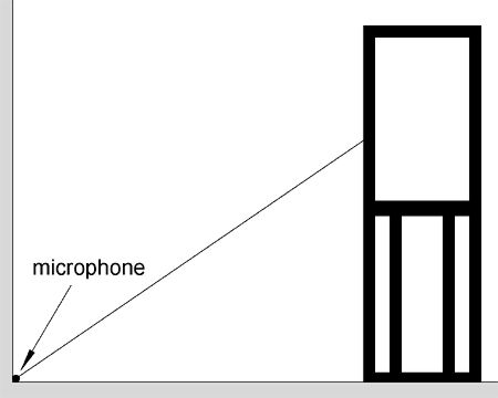
I can already get down to almost 100 Hz in a large room in my home. It has hard floor and walls (well gypsum board) with little furniture and I can place the mic at the floor-wall boundary midway along the wall. It might be perfect!
Markus;
Moving speaker and microphone relative to room will reveal influence of room.
Spectrograms are also good way to examine this too.
I know but the discussion arose when I said "windowing is just like smoothing". I should have said "windowing can have an effect similar to smoothing".
The linked Stereophile article explains why:
"By limiting the time window of a measurement, you also limit its frequency resolution. The relationship is a simple one: if you apply a time window of 6 milliseconds (0.006s—not unusual for measurements conducted in a typical domestic room), then the frequency resolution of the measurement will be limited to 1/0.006 = 167Hz.
This does not mean, as is sometimes inferred, that the measurement becomes unreliable below 167Hz—the problems begin much higher in frequency than that. What it does mean is that the frequency range is divided up into slices 167Hz wide, and any features of the loudspeaker's response that occur within one slice will be agglomerated in the measurement. That's of little consequence at a frequency of, say, 10kHz. But below 1kHz, this resolution amounts to a mere six frequency slices—obviously not enough to reveal useful detail."
If a speaker doesn't have any problems then the amplitude response from gated and ungated anechoic measurements will look the same but I want measurements to show nonambiguously that there are no problems. That's the whole purpose of making measurements. Like Earl said, I don't trust manufacturers. I even try on shoes before I buy them

Last edited:
Markus;
Apparently you don't trust math, physics, and concept of continuous functions either.
Of course I do. What makes you think I wouldn't?
Perhaps some day there will be a construct known as the Markus uncertainty principle.
It's in the works
By the way, how's your wide dispersion speaker coming along?The linked Stereophile article explains why:
"By limiting the time window of a measurement, you also limit its frequency resolution. The relationship is a simple one: if you apply a time window of 6 milliseconds (0.006s—not unusual for measurements conducted in a typical domestic room), then the frequency resolution of the measurement will be limited to 1/0.006 = 167Hz."
Marcus - I do not accept Howard's explanation here either. There "can be" an effect of a window, I've said that all along and Toole and Howard show the worst cases, but this is due to truncation and not a lower resolution as stated. It is simply NOT that simple. If the impulse has sufficiently decayed within the window then the resolution IS that of the data set. What is being missed here is the physical guarantee that the impulse response MUST decay to zero and NOT grow again (beyond a few ms. ) So there is no danger of truncating the impulse at an apparent low and then it rises up again - that's not possible. Any effect like that would be due o multipath, which is why we window in the first place.
After reading all of this I do see a need to show the impulse response to those who doubt everything (MARKUS!) because the truncation errors that everyone is showing would then be obvious. But if the impulse has decayed to zero and then a window is applied, there is no error and the resolution IS that of the data set.
Yes but it is never the case.But if the impulse has decayed to zero and then a window is applied, there is no error and the resolution IS that of the data set.
The higher the Q of an EQ (or any amplitude alteration) the longer the ringing, but even a low Q alteration does have an infinite ringing that will be truncated by any gating. This is what FIR is all about: how long is long enough for the task at hand (resolution).
- Status
- This old topic is closed. If you want to reopen this topic, contact a moderator using the "Report Post" button.
- Home
- Loudspeakers
- Multi-Way
- Uniform Directivity - How important is it?