An externally hosted image should be here but it was not working when we last tested it.
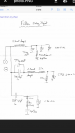
This looks reasonable.
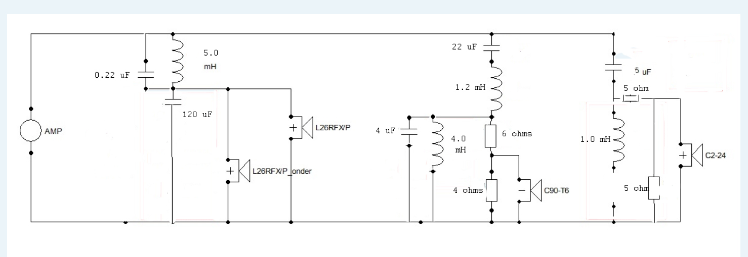
The "tank" 0.22uF across 5mH should produce a metal cone-breakup notch at 4kHz or so. The 0.22uF really ought to have a 47R or so resistor in series with it, otherwise it's an overly deep notch, but that's not a biggie.
The attenuators on the mid and tweeter should make the filters work as advertised and keep impedance good. I'm not sure I like the shallow tweeter filter, but it's one way of doing things. The 1mH connects to ground of course, slight typo there.
Downloads
I'd sim it now. And use preferred values like 4.7uF for 5uF.
Last edited:
If I wanted to do a quick and dirty sim of the suggested filter, I'd start by importing this design into the projekte folder of Boxsim:
boxsim-db.de | Boxsim Projektdatenbank
I'd use the Visaton AL200 driver, maybe the notch is at 5Khz, but not a biggie:
AL 200 - 8 Ohm
Now there is a learning curve with simulators, but essentially realign the cabinet to your dimensions, cut down the drivers to near what you have and get a rough and ready idea how it works.
There it is : http://www.filedropper.com/accutonspeakers
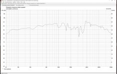
A problem in 1,5-2kHz area!? Or incorrect data in the file.
A problem in 1,5-2kHz area!? Or incorrect data in the file.
Attachments
Last edited:
There it is : http://www.filedropper.com/accutonspeakers
A problem in 1,5-2kHz area!? Or incorrect data in the file.
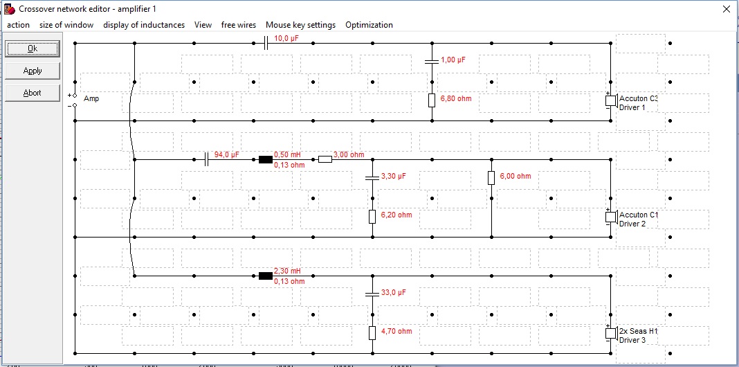
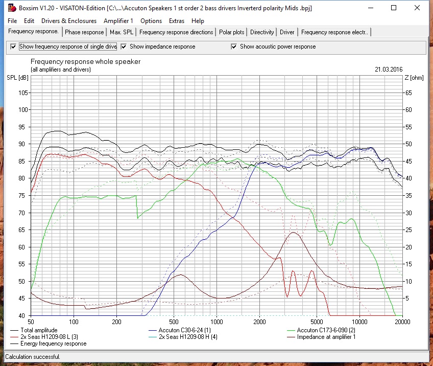
I had a fout in this XO now is much better : http://www.filedropper.com/accutonspeakers2ndorder
An externally hosted image should be here but it was not working when we last tested it.
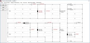
Now it looks mucht better: i did remove start from 2x Fc from the driver spec.
Same XO ., but with 2,3mH on the Bass 0,13 Ohm ( what i already have )
An externally hosted image should be here but it was not working when we last tested it.
Last edited:
I Think i made fault : Now looks better! By default the driver setting was : start from 2x Fc ( that cause the deformation. ) parallel
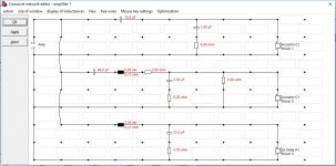
What I can do is first step Change polarity on my C173-06-090 and make little adjustments. My C173-06-090 was according my simulation doing very little se below:
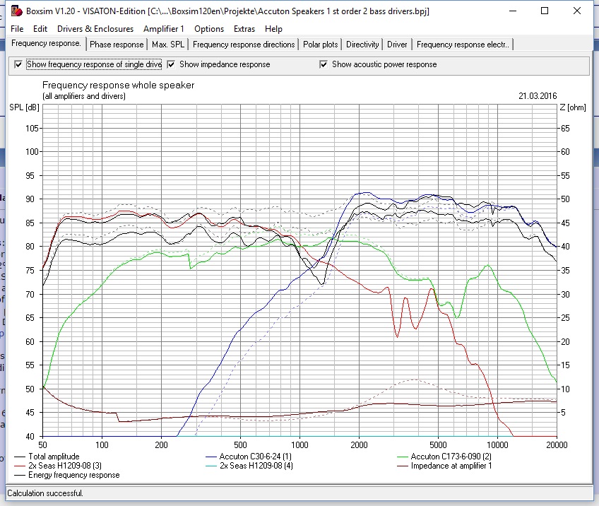
With little change i can do this :
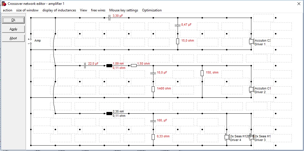
What I can do is first step Change polarity on my C173-06-090 and make little adjustments. My C173-06-090 was according my simulation doing very little se below:
With little change i can do this :
Attachments
-
 1st order XO , changed Polarity C173-06-090 Crossover.jpg152.9 KB · Views: 399
 -
 1st order XO , changed Polarity C173-06-090 Freq.jpg269.5 KB · Views: 388
 -
 1st order XO , normal Polarity C173-06-090 Crossover.jpg152.3 KB · Views: 404
 -
 1st order XO , normal Polarity C173-06-090 Freq.jpg260.3 KB · Views: 403
An externally hosted image should be here but it was not working when we last tested it.
This looks reasonable.
The "tank" 0.22uF across 5mH should produce a metal cone-breakup notch at 4kHz or so. The 0.22uF really ought to have a 47R or so resistor in series with it, otherwise it's an overly deep notch, but that's not a biggie.
The attenuators on the mid and tweeter should make the filters work as advertised and keep impedance good. I'm not sure I like the shallow tweeter filter, but it's one way of doing things. The 1mH connects to ground of course, slight typo there.
Downloads
I'd sim it now. And use preferred values like 4.7uF for 5uF.
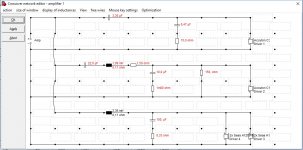
Hi Steve,
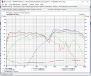
Can i use as Tank instead 0,22uF ( 0,01uF or 1.00uF ) ?
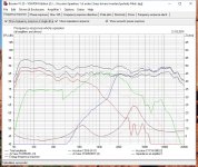
And if i go and Simulate the values via Box-Sim i get those results:
Attachments
Last edited:
- Status
- This old topic is closed. If you want to reopen this topic, contact a moderator using the "Report Post" button.
- Home
- Loudspeakers
- Multi-Way
- My New Concept