Steve, can you zip up your frd and zma files and upload them, and also upload the circuit that you have come up with using PCD? I've not had a lot of time lately but I might have a chance to have a bit of a play. Just looking at the graphs as you have uploaded I'm not sure, mainly because I can't see the phase info on them. The actual frequency response doesn't look too bad... roughly +- 2.5db from about 70Hz to 10Khz.
You may need some attenuation on the mid and high in reality, as I am assuming your frd files don't take into consideration baffle step, but it looks like a good start, and I'm sure it will be streets ahead of any off the shelf crossover that you may have purchased")
Tony.
You may need some attenuation on the mid and high in reality, as I am assuming your frd files don't take into consideration baffle step, but it looks like a good start, and I'm sure it will be streets ahead of any off the shelf crossover that you may have purchased
Tony.
Stevenn.
Sorry that this got so complex, even the explanation leaves a bit to be desired. Even if you don't do this at least now you are aware of the conjugate network, or more commonly referenced as a tank circuit. Later if you continue down the road of development you can think about this and play with the circuit. I imagine that someone else has been lurking and reading this thread and some will try this method of correcting the load seen by the amplifier and see the improvements that can be made.
I would take up Wintermute's offer to help you to finalize your own speaker crossover. You will be far beyond most canned crossover design that you will realize from a simple crossover software program.
Steven
Thanks for replies and reassurance.
Kindhornman - Your post does deserve a thread of its own - you cannot rely on reaching a wide audience of lurkers.
I noticed a section in PCD on the RHS of main sheet in the 'active' section called 'impedance input equalisation' which may well relate to what you have been suggesting.
Wintermute - file attached, could not copy generic circuit diagrams as they seem to be protected. Thank you for your offer, there is a bottle of red in it for your trouble!
Cheers
Attachments
Thanks Steve, I've downloaded and had a quick look. first tip. When you do the spl trace, try to do for as much of the frequency range that is visible on the spl graph. 2nd order slopes (which I think was the target) are still having an effect quite a way past the crossover point. I can understand why you would have done less, it is such a pain clicking away in spltrace I'll see how It goes but they might need to be extended
if you could do a screen grab of the woofer mid and tweeter cells on the left of PCD so I can see what you have set that would be a help and a good starting point for me rather than me just doing what I think That way I can look at it see if I would do something different, and if so I can say why.
edit: I can see why I couldn't see phase data too. There isn't any I'll have to look up how to do that (is something I';ve been meaning to look into anyway. Jeff has a tool from memory to extract the phase using a hilbert transform. Not something I've had to do as my measurements had good phase data). Having the proper phase data will definitely change how the simulation deals with the spl curves.
Tony.
I'll see how It goes but they might need to be extended if you could do a screen grab of the woofer mid and tweeter cells on the left of PCD so I can see what you have set that would be a help and a good starting point for me rather than me just doing what I think
That way I can look at it see if I would do something different, and if so I can say why. edit: I can see why I couldn't see phase data too. There isn't any
I'll have to look up how to do that (is something I';ve been meaning to look into anyway. Jeff has a tool from memory to extract the phase using a hilbert transform. Not something I've had to do as my measurements had good phase data). Having the proper phase data will definitely change how the simulation deals with the spl curves. Tony.
Last edited:
Steve, you might also want to have a look at this link http://audio.claub.net/Simple%20Loudspeaker%20Design.pdf It is probably going a bit further than what you want to, but worth a read. Personally I'd rather do actual measurements than go to that level of trouble with the baffle diffraction modelling (though it is probably worth while on the mid driver), but then It did take me quite a few years to get to the point where I was able to take measurements that are useful, so perhaps I'm forgetting the hard bits
here is the tool for extracting minimum phase from response data. Loudspeaker Design Software
I haven't looked at this yet, as I had to do some work this evening, and only finished about 1/2 hour ago.
edit: this is probably helpful as well, I know the first few times I tried to use spltrace it was pretty frustrating! http://techtalk.parts-express.com/showthread.php?182411-SplTrace-instructions
Tony.
here is the tool for extracting minimum phase from response data. Loudspeaker Design Software
This program also includes a Hilbert-Bode FFT Transform that allows you to extract the minimum phase from an frd or zma file. Once you have made all modifications to a file that you want to do then save the file as an frd file and then click the button for "Auto Extract Phase from FRD File", find that file, let the program extract the phase, and then save as the same file name (or another if you want) and the new file will contain the correct minimum phase data.
I haven't looked at this yet, as I had to do some work this evening, and only finished about 1/2 hour ago.
edit: this is probably helpful as well, I know the first few times I tried to use spltrace it was pretty frustrating! http://techtalk.parts-express.com/showthread.php?182411-SplTrace-instructions
Tony.
Last edited:
Thanks Tony for all yr help, far beyond what i was expecting.
Yes SPL trace is a little tedious.... i can redo them if you want. Phase info should be represented on PCD? There is no phase info on driver datasheets.
Sceeenshots attached, hope you can read them.
Please don't spend too much time on this and there is no urgency.
Cheers
Yes SPL trace is a little tedious.... i can redo them if you want. Phase info should be represented on PCD? There is no phase info on driver datasheets.
Sceeenshots attached, hope you can read them.
Please don't spend too much time on this and there is no urgency.
Cheers
Attachments
I found a better tracing tool!!! SPL Copy - Speaker Frequency Response Automatic Trace Tool works quite well, and a lot less tedius than spltrace I just did the SB23.
The spltrace puts zero in the phase column. It needs to have "real" phase values. I'll see what I can do with the fr tool, hopefully it will create the phase data.
attached the result from the trace tool for the sb23
This will probably be a bit slow, I've been really flat out at work. but I'll try and do a little each day. It's a nice distraction from other stuff
Tony.
I just did the SB23. The spltrace puts zero in the phase column. It needs to have "real" phase values. I'll see what I can do with the fr tool, hopefully it will create the phase data.
attached the result from the trace tool for the sb23
This will probably be a bit slow, I've been really flat out at work. but I'll try and do a little each day. It's a nice distraction from other stuff
Tony.
Attachments
Hi Steve, I managed to get phase data, the phase extractor spreadsheet on Jeff's site I linked to above is a no brainer. I'm not 100% sure it is ok though as the mid's phase seems to wrap too many times. I'll see how it goes.
Quick question. What are your baffle dimentions? and roughly where will the woofer, mid, and tweeter be on that baffle. The Response modeller spreadsheet looks pretty powerful so I want to have a play with it
Tony.
Quick question. What are your baffle dimentions? and roughly where will the woofer, mid, and tweeter be on that baffle. The Response modeller spreadsheet looks pretty powerful so I want to have a play with it
Tony.
Hi Steve,
I've played around with the mid frd file a bit. It seems to get better looking phase data if I start it from around 50Hz. I think it is good enough for modelling.
I've attached all three speakers with retraced spl impedance data and the phase data added. Plug them into PCD and see what difference (if any) you get.
I've not yet tried putting these into pcd. Time for bed
Tony.
Attachments
Last edited:
Because they have phase data The frd and zma files without the added phase data make it look like the drivers have perfectly flat phase across their frequency range. This will result in the sim assuming perfect phase alignment if the electrical filter phase matches. This doesn't happen in reality though.
I've been playing around, have moved it to speaker workshop as I find it better for fine tuning. I see why you say the drivers don't match well. The mid is a bit low on efficiency. I dropped the target to 87db and that seems to work better.
I also dropped all of the ancilory (zobels etc) to start off, I will add in if I think necessary.
Going out for dinner now.
Tony.
The frd and zma files without the added phase data make it look like the drivers have perfectly flat phase across their frequency range. This will result in the sim assuming perfect phase alignment if the electrical filter phase matches. This doesn't happen in reality though. I've been playing around, have moved it to speaker workshop as I find it better for fine tuning. I see why you say the drivers don't match well. The mid is a bit low on efficiency. I dropped the target to 87db and that seems to work better.
I also dropped all of the ancilory (zobels etc) to start off, I will add in if I think necessary.
Going out for dinner now.
Tony.
Hi Steve, could you give me the dimentions of the baffle? also I'm assuming the drivers will be centered, so could you also give the approximate distance from top (or bottom) of the centre of each driver.
As I really struggled to understand phase when I was starting out, I thought that this short youtube clip might help. Sine Waves and Degrees of Phase - YouTube
Basically if two sine waves are 180 deg out of phase they will cancel each other out resulting in a dropout in the sound. If they are in phase they will add together. In between they will either add or subtract to a certain degree.
Tony.
Tony,
Nice examples to simply explain phase angle. Now you have to add the different acoustic centers to multiple devices on a baffle and the time misalignment to the equation and things start to get more complex. Add in the electrical phase angle from a second or third order filter and it gets even more messy. This is why it is so much easier to go with higher order filters such as 4th order as the overlap is much less and the phase angle of 360 degrees takes that out of the equation to an extent. The more you look the more you realize how hard it is to really produce an excellent speaker + crossover design that give the conjugate result that you are looking for.
Steven
Yes Steven (KH), I've already got to a point where I was thinking about the driver offset's and the z offsets. These are things that I didn't have to worry about with my MTM's as they were all factored into the actual measurements. All measurements were done on axis with the tweeter (with drivers in their final cabinet), and time zero locked, so vertical and depth offsets were already in the measurements.
I've not tried going about design from the traced measurements in a serious way before, and I can see that whilst it will be better than an off the shelf crossover, I can't see it being as good as if real measurements are taken on the baffle.
Also going back into speaker workshop and playing with the sims, I've realised that getting the phase tracking right was probably the hardest bit, much harder than getting the slope correct, and quite a few iterations were necessary, trying different electrical orders (but still getting the same accoustic slope) was necessary before flat fr AND good phase tracking were achieved.
One thing I found with the hilbert transform was that the phase could be quite different depending on where I start the lower frequency from, this is not giving me a lot of confidence in the phase data.
Tony.
Hi Steve,
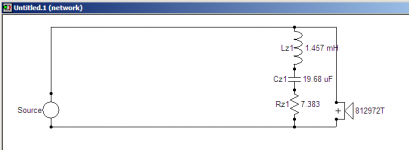
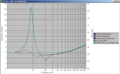
first thing I would say definitely has to change is the resonant peak filter on the tweeter. I modeled it it speaker workshop with the values you have in PCD, and it is missing the mark. Attached is a comparison of your pcd one, compared to the one automatically calculated by speaker workshop, and finally the one that resulted when I ran the optimizer in SW for the tweeter circuit I had.
The SW auto one is pretty much optimal as far as flattening the impedance is concerned, the optimizer probably changed it a bit to get the rollof to match the target curve I had better. The circuit diagram shows the SW auto calculated one.
The tweeter doesn't appear to have any ferro fluid (the impedance peak would be much lower if it did) so it probably does need the zobel if you want it to roll off properly, certainly I found it necessary (even though I started without it) to get the tweeter to fit the target curve (which I ended up setting at 4th order L/R at 3Khz).
Tony.
Attachments
Thanks Tony
I tried Speakerworkshop and found it virtually incomprehensible to the uninitiated compared with PCD which at last has an intuitive feel to it. After an hour I still had not loaded driver files so I gave up.
Will measure driver centres tomorrow, they are not aligned on same vertical axis. Nothing seems to be straightforward.....
I understand the concept of phase, but as driver data sheets invariably do not display it, I am mystified as to where info is coming from. Nothing seems straightforward! Why don't driver manufacturers talk about it more?
Thanks
Tony
Using cartesian co-ordinates in cm from bottom LHS corner:
Woofer - (14,16)
Tweeter - (6.5, 46.5)
MId - (20,37.5)
All co-ords to centre of dustcap. Woofer is aligned with centre vertical line.
Hope this makes sense.
Again, please do not spend much time on this, this is way beyond what i was expecting!
Thanks
Hi Steve, don't worry, I've always found that trying to help people increases my own understanding, so it helps me too
On the questions on phase, KindHornman touched on that above, that is one of the reasons for requesting the driver positions. You will notice that PCD has a section where you can enter the relative driver offsets. This is one place where it has an advantage over speaker workshop. What I'm having trouble with at the moment is how I get (very) different phase data depending on where on the freq scale I start the hibert transform.
Speaker workshop is easy once you get the hang of it, but getting there has quite a steep learning curve.
Right click in the left pane and click import to import your driver frd and zma.
go to resource new driver and add a driver. double click it. right click on the graph that comes up and select properties. go to the data tab. click on the question mark beside frequency response and zma and choose the measurements you imported.
You now have a driver that you can add into a network.
I find speaker workshop better for looking at the phase than PCD as I can adjust the graphs more, it's also better for doing notch filters, but pcd will probably be better for your situation
Tony.
- Status
- This old topic is closed. If you want to reopen this topic, contact a moderator using the "Report Post" button.
- Home
- Loudspeakers
- Multi-Way
- WIN ISD Pro and multiway design