Steve, not a difference between speaker workshop and PCD. My PCD was VERY similar to speaker workshop graph....
Which frd files did you use? I was using the BS2 ones. They have been modified in the response modeller spread sheet to have the full effects of the baffle step which would probably account for the roughly 6db difference you are seeing at the bass end if you are using the older measurements that I uploaded.
Note that if you are going to put these speakers really close to the wall that they may end up being quite bass heavy with the crossover I have posted. I hadn't actually realised it was doing the full 6db, I thought I had dialed it back to 3db, but perhaps not!
Attached is what I'm seeing in pcd with the all_tweaks.csp project file loaded, the BS2 frd's and the tony_phase zma's. The all_tweaks stood for doing the baffle step in response modeller, and also that I had normalized the data in splview before extracting the phase.
Note that I have BOTH the mid and the tweeter inverted in phase. I think that might be part of what is wrong with your first graph (actually no, I just changed and get reasonable nulls).... also another thing that might make a bit of difference is that I have put abitrary DCR's in for all of the coils, most of the 0.3 ohms. This should be substituted with actual values for coils you would consider purchasing, but 0.3 is probably reasonable for the smaller ones, some of the bigger ones, unless you go pcore or iron core will more than likely have a higher dcr.
edit: Steve with your second graph, you seem to have a big overlap between the 8" and the 4" may not be an issue as they seem to have reasonable phase tracking, but I'd turn on the phase on the graph and have a look at what it is doing. It certainly allows you to up the sensitivity. Might be a good option, but I'm not sure. I went traditional at the expense of sensitivity. It certainly looks good from an FR curve point of view!
Tony.
Attachments
Last edited:
Tony,
Thanks you are right I was thinking of the Chebychev filter ripple response. But I appreciate the time to show the difference. The filter response in your last composite post looks nice if that is the true result that Stevenn get's in reality. He can always tweak the response curve after he builds the network and the actual enclosures and mounts the drivers. Nice work, especially as a free favor, unless that bottle of red is valuable!
Thanks you are right I was thinking of the Chebychev filter ripple response. But I appreciate the time to show the difference. The filter response in your last composite post looks nice if that is the true result that Stevenn get's in reality. He can always tweak the response curve after he builds the network and the actual enclosures and mounts the drivers. Nice work, especially as a free favor, unless that bottle of red is valuable!
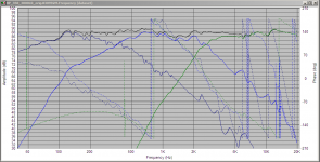
Thanks Steven! I did one more tweak, can't help myself I changed the shunt inductor in the tweeter network to 160mH and the phase tracking is much better now. It highlights the dip between 1 and 2khz a bit more but there's not much can be done about that that I can see short of more attenuation of the tweeter and some attenuation on the woofer.
attached is the graph from speaker workshop as it is better for looking at the phase. I never went and did any adjustments on the 350 Hz end, the phase tracking there should be able to be made better with some tweaks.
I have confidence in the simulations themselves, but it all depends on how accurately the modified manufacturers spl curves match the performance on Steve's baffle. The other unknown is the driver offsets.
I'd be very interested to see actual measurements of the final implementation (whatever Steve decides to go with). Perhaps later in the year if Steve is willing we could do that (though I was supposed to meet up with another member to do some measurements and stuff just kept getting in the way and it never happened )
This was a nice exercise for me, nice bottle of red or not. I've been thinking about doing a three way, but wasn't sure how I'd go. This gives me confidence that I have learned enough from my two ways to do it
Tony.
Attachments
Thanks Tony
As you have confirmed SW and PCD should have similar responses, then as I suggested in my post, I have probably got a component wrong which is why my graph is different.
Can you post PCD screenshots of main design sections for each driver?
Also I don't have any values for coil DCR entered, I didn't know that trick!
Very happy for you to have a play with finished unit, I will update you on progress.
And please PM with contact details to organise a bottle of finest red!
Cheers
Hi Steve, On the train at the moment, if you look in the top left corner of the PCD spreadsheet, there should be a load saved session file button. If you click on that and choose the all_tweaks.csp file that was in the last zip file I attached you should get exactly what settings and driver values I had ") If it isn't working let me know and I will take the screen shots.
If it isn't working let me know and I will take the screen shots.
I'll PM later tonight
Tony.
If it isn't working let me know and I will take the screen shots. I'll PM later tonight
Tony.
HI Tony
Something is a little amiss, tweeter and woofer values in PCD match SW circuits but mid range values don't match and are very different. PCD (all tweaks) is showing mid as having for High Pass a second order filter and for LP a third order electrical. Is this correct?
When you have time, can you post mid range PCD screen shot?
Thanks
Hi Steve,
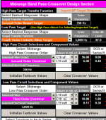
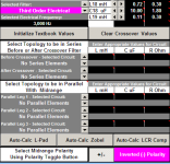
attached are two screen shots of the midrange values. Yes the 2nd order on the highpass and 3rd order on the low pass is correct. This is because they high pass at 350Hz is basically flat way out past the crossover frequency so needs 2nd order electrical to get 2nd order accoustic rollof. The Low pass at 3000Hz however the mid is starting to roll off a bit so that in combination with 3rd order electrical (and the fact that is what worked best for me to get the phase matching) means that the 3rd order electrical gives a 4th order accoustic slope.
I did try it with 4th order electrical which also was able to match the accoustic target, but the phase wasn't as good and it required an extra coil so I went with third order
The tweeter is also 3rd order electrical, but if you look at the target slopes they are 4th order L/R
Tony.
Attachments
Hi Steve, I've been playing around and there is definitely something strange happening... I have not been able to get the curve that you have in your graph, even using the non-baffle step corrected frd's.
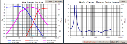
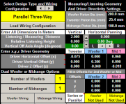
Here is a screenshot of what the filter transfer functions look in my pcd, and also the impedance plot.
One thing that I did notice. The asymmetric placement of the drivers on the baffle seems to have quite an effect on off axis frequency response. I actually changed the settings to have the offsets relative to the centre (I had them relative to the tweeter) It doesn't make much of a difference on axis but does change how it sims off axis.
With the offsets relative to the centre line there is a deep null at the crossover frequency at about 30 degrees horizontal off axis. Just something to be aware of, I suspect that they will be best listened to on axis. I doubt there is much could be done in the crossover to compensate for this (though I could be wrong).
Tony.
Attachments
Tony,
I don't know any way that you can offset electronically a physically offset driver on a baffle. I understand where the baffle offset comes from but it really makes the network design and speaker interface asymmetrical in nature and that was the original point of those designs. It can be used to change the diffraction affect about the baffle to change the center vs side wall reflections, but how you model that I can't say. It would take real physical testing in a specific room to optimize that effect. I think it will just complicate the entire process rather than symmetrical placement along the center-line of the enclosure.
I don't know any way that you can offset electronically a physically offset driver on a baffle. I understand where the baffle offset comes from but it really makes the network design and speaker interface asymmetrical in nature and that was the original point of those designs. It can be used to change the diffraction affect about the baffle to change the center vs side wall reflections, but how you model that I can't say. It would take real physical testing in a specific room to optimize that effect. I think it will just complicate the entire process rather than symmetrical placement along the center-line of the enclosure.
Yes Steven I think you are right. I'm not going to worry about it. In PCD I noticed that you could vary the listening axis (both vertical and horizontal) I was rather shocked when I got to 30 deg off axis that there was a huge null at the crossover frequency. Changing the offsets (from centre) back to central completely eliminated it.
If I interpreted Steve's co-ordinates correctly the tweeter is offset to one side of the centre line, and the mid is offset to the other side of the centre line. This is an odd arrangement that I haven't seen before. Usually the speakers are offset differing amounts to the same side.
Tony.
If I interpreted Steve's co-ordinates correctly the tweeter is offset to one side of the centre line, and the mid is offset to the other side of the centre line. This is an odd arrangement that I haven't seen before. Usually the speakers are offset differing amounts to the same side.
Tony.
Tony
I reinitialised PCD and reloaded driver files and got a different response curve again, i think there may have been some residual components from previous attempts lurking unseen in the background of my PCD.
I added a 5 Ohm resistor at R1 in Woofer response section and attached is result.
Hope this compares favourably with your summed response.
Placing order on Speakerbug tonight.
Cheers
Attachments
Last edited:
Hmmm I think there is still something funny going on. Maybe don't place that order till we work out what, not sure if the issue is on your or my side!!
5 ohms in series with the woofer will completely change the tuning in the box, so if you are needing that to make it look flat it is probably not going to work as you expect. Try doing the modelling in winisd with 5 ohms added series resistance and see what it does to the response curve!
Could you please save your config zip it up and attach it? I'd like to know what is causing the differences between our results, as there shouldn't be such big differences!
Tony.
OK I just did some playing and if I use the sb23 frd file that does not have any baffle step compensation in it then I DO get a curve very similar to yours if I add in the 5 ohms series resistance.
Attached is another zip files with all of the frd's and zma's I've been using, renamed to be consistent and less confusing!
These have been "corrected" for the baffle dimensions. Any driver on a baffle will have a drop in sensitivity at a frequency related to the dimensions of the baffle at frequencies lower than that point. The manufacturers curves are taken on an infinite baffle, meaning that the baffle step doesn't occur. You will only get a response like that if the drivers are mounted in wall.
I actually corrected based on your baffle dimentions using one of Jeff's tools. This is why I'm not getting the rise in the bass without attenuating the woofer
Tony.
Attachments
Tony, lucky you were on line!
Have reloaded driver files and removed 5 Ohm resistor - again a nice flat summed response curve (attached). I am using ALL TWEAKS CSP but have also uploaded my final csp for comparison.
Cheers
Have reloaded driver files and removed 5 Ohm resistor - again a nice flat summed response curve (attached). I am using ALL TWEAKS CSP but have also uploaded my final csp for comparison.
Cheers
Attachments
Last edited:
Hi Steve, I was just having a quick look, I think you need to (especially for coils) pick some close values on speaker bugs site, and adjust the values in PCD to match (including the DCR) and see how it looks. If all still looks ok, then that should be fine to go with. caps you can fairly easily parallel up some to get a value you need, but again if you can get away with standard values all the better.
A lot of people say you have to use air cored coils for good quality. for the big ones (say the 4.6mH) I think you should probably look at the pcore coils. even the heavy gauge ones in air core have around 0.8 ohms dcr which is quite high, additionally the problem with cored inductors is saturation, but the pcores say they are good up to 400W before saturation occurs so I think that they should be fine.
I tried to stay around the 0.3 to 0.4 range in the sim, as that is not going too overboard. but you can go lower, provided you check it doesn't have any adverse affects in the sim
hehe just when you thought it was all done, I thow this one in there.... sorry!
Tony.
yep I think so I couldn't see any 4.6mH coils, closest was 4.7 but I put that in SW and the difference was neglible.
Just noticed something as well. The 1mH tweeter zobel coil doesn't have any DCR assigned (and no way to do it in PCD) so since there is 5.6 ohms in series with it, you can subtract the value of the coils DCR from the resistor. In this case it doesn't matter if you use a high dcr coil as it has significant resistance in series with it anyway, so no point paying for a larger lower dcr coil when we are just putting a resistor in to up the resistance. So you could for instance use this 1 mH 18AWG Air Core 0.48 ohm DCR 1239 [3240] - $11.40 : SpeakerBug, capacitors, inductors, resistors, crossover parts, speaker supplies one even though it is close to .5 ohms... just drop the other resistor from 5.6 ohms to 5.1 ohms.
Also the resistor on the tweeter you will probably want to go with a reasonably high powered one. I think I went with 10W or 12W ones on my tweeter...
Tony.
I couldn't see any 4.6mH coils, closest was 4.7 but I put that in SW and the difference was neglible. Just noticed something as well. The 1mH tweeter zobel coil doesn't have any DCR assigned (and no way to do it in PCD) so since there is 5.6 ohms in series with it, you can subtract the value of the coils DCR from the resistor. In this case it doesn't matter if you use a high dcr coil as it has significant resistance in series with it anyway, so no point paying for a larger lower dcr coil when we are just putting a resistor in to up the resistance. So you could for instance use this 1 mH 18AWG Air Core 0.48 ohm DCR 1239 [3240] - $11.40 : SpeakerBug, capacitors, inductors, resistors, crossover parts, speaker supplies one even though it is close to .5 ohms... just drop the other resistor from 5.6 ohms to 5.1 ohms.
Also the resistor on the tweeter you will probably want to go with a reasonably high powered one. I think I went with 10W or 12W ones on my tweeter...
Tony.
Hi Steve, I've just had a bit of a browse of the schematics again, and the one place were lower DCR would really be beneficial is on the two coils in the midranges bandpass filter that are in series with the driver. That is L18 and L19 in PCD. It looks like there is only one value in the 0.7 mH size and that has dcr of 0.4 ohms, I think it might be worth dropping it back to 0.68mH and getting the bigger one that has 0.2ohms or 0.24 ohms DCR. For the 0.1mH one get the 18 gauge which has a very low DCR of 0.12 ohms (they are all very similar in price at this size). The combination of the two will give a small SPL increase in the midrange compared to the original arbitrary DCR's I specified, which is were there is a bit of a trough.
Tony.
Tony.
Wintermute,
Another way to lower the dcr of the inductors is to use a solenoid winding around a small wooden dowel that has the equivalency to air. In this fashion the wire length is much shorter for each winding and the dcr will drop. The cost of wire goes down with it and the saturation point is really much higher as you see with the cored inductors. Just another factor that can be played with in inductor fitting to a crossover that is often overlooked due to the reliance on the magic dimensions on an air core inductor.
Another way to lower the dcr of the inductors is to use a solenoid winding around a small wooden dowel that has the equivalency to air. In this fashion the wire length is much shorter for each winding and the dcr will drop. The cost of wire goes down with it and the saturation point is really much higher as you see with the cored inductors. Just another factor that can be played with in inductor fitting to a crossover that is often overlooked due to the reliance on the magic dimensions on an air core inductor.
- Status
- This old topic is closed. If you want to reopen this topic, contact a moderator using the "Report Post" button.
- Home
- Loudspeakers
- Multi-Way
- WIN ISD Pro and multiway design