I have yet to see a good presentation of the CBT frequency response, ala a polar map, to see how well they actually do what's claimed. Don's discussion is theoretical not real data. Shaded curved line arrays are far from new, why all-of-a-sudden are they of such interest?
exactly, and one can use the old ArraySHOW simulation program by Mark Ureda to get an idea of what happens to vertical and horizontal directivity in such a convex Legendre shaded array, certainly this is not a Holy Grail of a domestic loudspeaker
It is good to know Omholt's agenda
") now one knows who's talking
now one knows who's talking
Last edited:
The question I would ask, as I have in similar threads, is this:
What level of 'controlled directivity'?
I would say that vertically the pattern should be narrower than horizontal, but how much? 60'x120'? 60'x90'? Since we're talking 'controlled', then CD is obviously included.
What level of 'controlled directivity'?
I would say that vertically the pattern should be narrower than horizontal, but how much? 60'x120'? 60'x90'? Since we're talking 'controlled', then CD is obviously included.
Last edited:
All things considered, I think a well engineered waveguide speaker will perform better with minimal treatment when space is an issue. If you have lots of space around the speaker, a CBT may be a better choice.
I am mostly with you here, except that as the room gets larger then other factors of the waveguide, like efficiency and power handling, come into play creating a preference for the waveguide, IMO. I know the CBT is claimed to have good power handling, but that is certainly an area where I have my doubts. We are still talking about very small speakers handling very wide bandwidths. Numbers help, but not all that much.
We don't talk much about the vastly superior sensitivity and power handling of a compression driver waveguide because in a small room its not really a big factor. But as the room gets bigger this fact is undeniable and the reason why ALL large venue playback systems are horns.
What level of 'controlled directivity'?
I would say that vertically the pattern should be narrower than horizontal, but how much? 60'x120'? 60'x90'? Since we're talking 'controlled', then CD is obviously included.
Horizontal should be below 90 - this allows toe-in that keeps the speaker from illuminating the nearest walls. In the verticle, narrower is desirable, but at what cost? If compromises of the horizontal need to be made to achive a narrower vertical then I am still of the opinion that this is a bad tradeoff. Better to handle the floor and ceiling with room treatments, but leave the side walls reflective. Verticle reflections do not add to spaciousness, in fact there are no positives for them. Reflective side walls, fairly absorptive ceiling and floor - the ideal situation for an axisymmetric waveguide and one easily achieved in practice.
I think that you need to look at each implementation specifically verses generic answers to the questions here. There are many different designs in each category and each implementation has its own effects. While we have what are called CD waveguides I would say that many so called CD waveguides are anything but. As Gedlee will say himself many of the so called CD conic waveguides are anything but in reality. The same thing goes for vertical line-array's, what we are really talking about here. Line arrays have very specific comb filter effects that have been well known for decades. though the tiny devices and minimal center to center distances for all the devices we are looking at in these home systems would limit some of the problems with lobbing like a professional PA system will have to deal with. But think of the string of devices in these line arrays. Nobody is going to produce very high impedance devices for these line arrays, the speakers are standard devices strung together and this isn't being talked about. Think about the impedance curve when you connect devices in series-parallel and one device is seeing the voice=coil inductance's of one or two or three other devices in a series, not a great idea in my mind. This tells me that the individual devices are not at all equal across the line, we have a shifting frequency response up and down the array if I am correct. And Gedlee is correct that the polar plot shown earlier is only a theoretical drawing, not a real resultant. Lets see a real polar plot of a real line array such as discussed here for a home. I am not advocating for either type of device just saying that each has its place and each has its own limitations when looked at in the real world and not the theoretical realm.
Thanks Gedlee. That answered it perfectly, and it agrees with my thoughts. Even though i was 'stabbing in the dark'. I am using a waveguide loaded ribbon, and id estimate a 60x120 pattern, perhaps 60x90, its hard to say by merely looking. I found the control of vertical radiation a large improvement over the domes im used to. Having said that, Ive also had some success with felt around the tweeter, and foam in the throat of the waveguide. Unfortunately, i dont have room for 'real' speakers of the kind that youre known for, and like many I still hope to control radiation pattern to some degree.
Hi
An alternative is even more directivity
To the degree one can place two loudspeakers side by side in a wider angled “array” and not hear anything funny as you walk back and forth, one can possibly place that speaker on a boundary and not produce an audible reflection.
In installed sound, contractors often install our Synergy horns that way although is usually on the ceiling but I have done this for stereo on side walls. .
That works very well because you can place two SH-50’s, sm-60’s etc hard packed (the side walls of the cabinet are equal to the horn wall angle and only a few inches away) tight packed and you cannot hear a seam or any artifact walking back and forth.
As they each radiate a “pie slice” over a broad band from a point at the very rear of the cabinets and have pattern control to a “lowish” frequency , they couple into one wider source well enough to have an inaudible seam. One can substitute a physical boundary to produce a mirror image of the second source.
The “CLF” data format we have the loudspeakers in has things like polar plots and a 3d view of the radiation.
For an SH-50, even aimed normally (right speaker at left most seat and vis versa) they radiate less than normal to the sides and rear, for example 90 degrees off axis at 500Hz they are still nearly -20dB down H and V and at 250Hz about -7 or 8 dB down 90 off axis.
There are NO crossover or multi-source lobes or nulls to worry about, the result of the linear phase crossover is they really act like there is only one driver in time to the degree they reproduce a square wave over more than a decade wide band and in space, that you can walk up, stick your head into the horn mouth and never hear anything other than one source floating in front of you.
With pattern control that low, it is easy to place the speaker a fraction of a wl from the boundary with the -6dB radiation angle parallel to the room wall / boundary and viola, effectively no wall reflection.
Vertical reflections are usually unavoidable but with the horn at half room height, there is a reflection free zone that extends to just short of twice the distance from the vertical pattern angles and ceiling and floor intersection.
In other words, if the floor and ceiling were mirrored, you would want to be seated closer than the distance where you can see the Horns compression driver in the mirrors.
At that much closer distance, much less of the reflected energy will reach you.
The side wall approach takes care of that acoustic image from the close wall and the same mirror idea would apply to the reflection from the opposite wall. While these aren’t made for hifi they certainly work for that.
On the CBT, I will be seeing Don Friday at an AES /ASA meeting we are both presenting at so maybe I can pick up more info about how they measure.
I haven’t been active in either AES or ASA for a while but it will be fun showing Don these horns as a number of the aspects he discovered / described apply to these.
Best,
Tom Danley
Danley Sound Labs
Strange comment. I didn't think you cared too much about looks of a speaker? I'm not here to defend anything and have no agenda, but simply sharing my personal view on the estetiques. I have waveguide speakers as well, and I enjoy both.So no bias here for your "new" speakers.
I'm probably also the only one here who have seen several CBT speakers with different finishes.
Here's pics of your speaker and a CBT and then people can decide for themselves.
It's out there in the public. Don has published a lot and more is coming.I have yet to see a good presentation of the CBT frequency response, ala a polar map, to see how well they actually do what's claimed. Don's discussion is theoretical not real data. Shaded curved line arrays are far from new, why all-of-a-sudden are they of such interest?
The CBT tehnology is quite new and they solve a lot of issues. It has the strength of a regular line array, but not it's weaknesses which some are mistakenly thinking.
A more uniform polar response and a more even frequency response is something I at least welcome.
a_tewinkel:
I have like previously mentioned not seen any high gain reflections arriving of the frontwall from the CBTs. I've measured, and I will do it again when I get back my crossover unit.
I believe many are making wrong judgements based on assumptions and misunderstanding the concept.
CBT36 can handle much power and play extremely loud. They do need subs for the lowest frequencies, rolling off at about 45Hz, but there's also bigger CBTs that have deeper bass. The CBTs are very flat and even down to about 100 Hz. Beat that!
Hi Tom,
If you have time, I'd love it if you could comment on the feasibility of a unity horn experiment that I am planning. This goes back to post from a few pages back about using the floor to extend the horn/create mirror sources. (i.e. cutting a horn in half and using the floor to close it). I watch my projector from the floor.
This problem here would be maintaining enough symmetry for the treble to be well behaved. My plan is to make a ribbon or planar magnetic tweeter to feed the throat. This could be small and easily made flush with the horn. A square format would be easy to mate with a square throat, too. I expect that at my low SPL requirements (average 80 dB at 1 m) I should be ok with all the horn gain available.
Is this a reasonable plan for a low SPL speaker with good directivity?
The CBT tehnology is quite new and they solve a lot of issues. It has the strength of a regular line array, but not it's weaknesses which some are mistakenly thinking.
A more uniform polar response and a more even frequency response is something I at least welcome.
a_tewinkel:
I have like previously mentioned not seen any high gain reflections arriving of the frontwall from the CBTs. I've measured, and I will do it again when I get back my crossover unit.
I believe many are making wrong judgements based on assumptions and misunderstanding the concept.
CBT36 can handle much power and play extremely loud. They do need subs for the lowest frequencies, rolling off at about 45Hz, but there's also bigger CBTs that have deeper bass. The CBTs are very flat and even down to about 100 Hz. Beat that!
My comment on the front wall was not specifically on the CBT, but front wall reflections (even at moderate levels) have been found to cause colouration with other box speakers. They may be difficult to measure in the presence of multiple other reflections. However, I think it is safe to assume that the CBT, being a narrow closed baffle speaker, will have the same potential problem. Depends on the distance to the wall of course.
I have been very interested in the CBT technology and have studied it thoroughly. It is a very well engineered loudspeaker with some very desirable characteristics, most notably the vertical radiation pattern and interfacing with the floor. The CBT36 has sufficient power handling and volume displacement to be coupled with a subwoofer and play at high levels.
However, personally I think a good waveguide loudspeaker has a slight advantage in small rooms. I think that the image will be better defined and that it will be less sensitive to placement near walls. It is more sensitive to the floor reflection, but as I mentioned, that can be easily dealt with.
Last edited:
Women love the CBT. As long as they're at strange angles and not hooked up. They look kind of phallic. And maybe even a little flaccid..
http://www.parts-express.com/cbt36/images/local_large/IMG_201.jpg
http://www.parts-express.com/cbt36/images/local_large/IMG_201.jpg
Last edited:
I can verify that. I tested it several times and demonstrated it to several people. It's an usual effect.If you listen to the system on the side, it gets louder and louder as you squat down!
Hi Tom,
If you have time, I'd love it if you could comment on the feasibility of a unity horn experiment that I am planning. This goes back to post from a few pages back about using the floor to extend the horn/create mirror sources. (i.e. cutting a horn in half and using the floor to close it). I watch my projector from the floor.
This problem here would be maintaining enough symmetry for the treble to be well behaved. My plan is to make a ribbon or planar magnetic tweeter to feed the throat. This could be small and easily made flush with the horn. A square format would be easy to mate with a square throat, too. I expect that at my low SPL requirements (average 80 dB at 1 m) I should be ok with all the horn gain available.
Is this a reasonable plan for a low SPL speaker with good directivity?
I presume you mean my post, yes i'd be interested in at least exploring the idea further and hearing Toms take on it. I'm not in a position of being able to actually install the speakers directly into the wall/corner as a sofit-mounted corner unity horn (renting), but if I was going to build a unity/synergy horn, that would be how
Last edited:
I would appreciate if you guys can post polar responses of the best waveguides/horns you know about. Perhaps the best ones have passed me by.
Off-axis measurements would also be ok. Both horizontally and vertically.
An externally hosted image should be here but it was not working when we last tested it.
now post CBT graphs
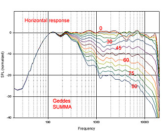
Is that Geddes Summa?
That's not what I'm looking for. It's a classical collapsing polar response. Not very uniform.
Don Keele hasn't posted 3d simulations like this yet of CBT36. He has said he is going to and will also measure them anechoic with a perfect even and reflective floor which the speakers require. So we have do wait for a better comparison.
This one is measured in a room with uneven floor and includes the room's comb filtering. 1/12 smoothing.
This one is from his paper:
That's not what I'm looking for. It's a classical collapsing polar response. Not very uniform.
Don Keele hasn't posted 3d simulations like this yet of CBT36. He has said he is going to and will also measure them anechoic with a perfect even and reflective floor which the speakers require. So we have do wait for a better comparison.
This one is measured in a room with uneven floor and includes the room's comb filtering. 1/12 smoothing.
An externally hosted image should be here but it was not working when we last tested it.
This one is from his paper:
A complete set of ±60º horizontal x ±60º vertical footprint plots at all one-third octaves over the frequency range of 630 Hz to 16 kHz. In each footprint plot, the pressure in dB is normalized to the maximum in the stated angular range and is shown as a grey-scale density plot (high pressure in white and low in black).
An externally hosted image should be here but it was not working when we last tested it.
Is that Geddes Summa?
That's not what I'm looking for. It's a classical collapsing polar response. Not very uniform.
Don Keele hasn't posted 3d simulations like this yet of CBT36. He has said he is going to and will also measure them anechoic with a perfect even and reflective floor which the speakers require. So we have do wait for a better comparison.
This one is measured in a room with uneven floor and includes the room's comb filtering. 1/12 smoothing.
An externally hosted image should be here but it was not working when we last tested it.
geez... what a mess! can't You see it??
fairly uniform ???? CBT array center speaker data
Interesting data. Seems like the rear wall reflection is visible up to 500 Hz in otherwise free-field conditions...
By the way, I see that this is a different CBT (a three-way). Still gives some interesting info.
Interesting data. Seems like the rear wall reflection is visible up to 500 Hz in otherwise free-field conditions...
By the way, I see that this is a different CBT (a three-way). Still gives some interesting info.
Last edited:
- Status
- This old topic is closed. If you want to reopen this topic, contact a moderator using the "Report Post" button.
- Home
- General Interest
- Room Acoustics & Mods
- Controlled vs wide dispersion in a normal living room environment..