A recent house move has dictated that I now have to house my system in a shared space. The result; I have been banned by my wife from running my large and admittedly homely hardwood framed "nude" Accoustat 1 + 1 speakers in the new house.
At this point I am stuck with running a pair of Celestion 100's, formerly a 2nd system speaker, in my system. For those who don't know them, these were the last in the series commencing with the Celestion SL 6, a smallish standmount 2 way. This is an improved update on that legendary model.
They don't sound too bad if you can forgive a loss of low level detail and a propensity to congest when playing complex material. Some of this may be inherent in the smallish two driver format, but I have already improved both weaknesses noticeably by replacing the internal damping foam with Twaron Angelhair. This is an extremely fine fibre looking much in aggregate like candy floss. This cost me just over 50 Euro for 200 gm's including postage from Holland to New Zealand. I ended up using about 5 gm's per litre in each 12 litre cabinet.
The improvement is sufficient for me now to consider upgrading the crossover, All crossover caps are film and from their size I would guess are polycarbonates. The series cap for the tweeter is 6.0 uf, don't you love the non standard value? This I will replace with some polypropylene caps making up the same value.
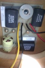
There appears to be an aircore inductor across the tweeter, and a ferrite core inductor in series with the bass- midrange driver. The latter is often worthwhile upgrading, but of course there is no value marked on the part. A google search has turned up blankand Celestion have been bought out many years ago. Can anyone assist with the value of this part?
Thanks
Rob.
At this point I am stuck with running a pair of Celestion 100's, formerly a 2nd system speaker, in my system. For those who don't know them, these were the last in the series commencing with the Celestion SL 6, a smallish standmount 2 way. This is an improved update on that legendary model.
They don't sound too bad if you can forgive a loss of low level detail and a propensity to congest when playing complex material. Some of this may be inherent in the smallish two driver format, but I have already improved both weaknesses noticeably by replacing the internal damping foam with Twaron Angelhair. This is an extremely fine fibre looking much in aggregate like candy floss. This cost me just over 50 Euro for 200 gm's including postage from Holland to New Zealand. I ended up using about 5 gm's per litre in each 12 litre cabinet.
The improvement is sufficient for me now to consider upgrading the crossover, All crossover caps are film and from their size I would guess are polycarbonates. The series cap for the tweeter is 6.0 uf, don't you love the non standard value? This I will replace with some polypropylene caps making up the same value.
There appears to be an aircore inductor across the tweeter, and a ferrite core inductor in series with the bass- midrange driver. The latter is often worthwhile upgrading, but of course there is no value marked on the part. A google search has turned up blankand Celestion have been bought out many years ago. Can anyone assist with the value of this part?
Thanks
Rob.
I don't think there is any substitute for actually measuring components in crossovers. A multimeter capable of measuring capacitance and inductance is indispensible really. Make a note of wiring polarity and bass orientation because they often rub voice coils if you turn them upside down. ")
Post some pictures of this speaker because it sounds like you can help other users here. Measure the cabinet driver cutout sizes.
Bass is usually a series coil and a shunt capacitor, sometimes with a small damping (1 0r 2 ohm) resistor in series with the capacitor. Tweeter is often a series capacitor and shunt coil along with some wirewound resistor padding. Changing ageing non-polar electrolytics for film types can produce frequency response changes, sometimes for the worse.
The best affordable metal dome available these days is probably the SEAS 22TAF/G, and it might be a good upgrade.
Yes Good advice I think. Though I haven't taken the crossovers out of the cabinets yet the circuit is pretty much as you describe from what I have seen, there is a 3.3 ohm padding R in the tweeter leg and a 2.7 ohm in series with the 10uf cap across the bass midrange driver. The tweeter has an aircore coil in series with a 8 uf cap from what I can see. The caps are film but appear too small to be polypropylene.
The cabinets use dual longitudinal braces which seem to me to be a curious choice since they lock in the top and bottom panels with the side panels but those are smaller panels than the front and rear which might have benefitted from bracing more. As it happens John Atkinson measured a cabinet resonance just over 400hz which was strongest on the back panel. A little extra bracing will be in order.
The cabinets use dual longitudinal braces which seem to me to be a curious choice since they lock in the top and bottom panels with the side panels but those are smaller panels than the front and rear which might have benefitted from bracing more. As it happens John Atkinson measured a cabinet resonance just over 400hz which was strongest on the back panel. A little extra bracing will be in order.
I look forward to seeing a schematic.
Hang fire on extra bracing or battens. It can make things worse. You might add some very high Q resonances unless you are careful. Hardwood especially can be very bad mixed with softer materials.
Those vertical braces down the sides are familiar and designed to reduce output from the side panels. Front and back baffles don't necessarily benefit from extra rigidity. What can be good is adding damping pads to side, top and bottom panels.
Then with closed box, you add lots of wadding, with reflex, only a little.
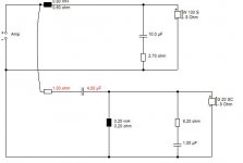
Here is the Celestion 100 schematic, values for the inductors were measured using an LC meter calibrated using a known value inductor... Edit* my hand drawn schematic exceeds the size for this site. I will need to work out another way of posting it.
Anyway I have temporarily mounted the crossovers to the outside of the back panel to facilitate ease of component substitution. This has had a slightly unespected positive impact on the sound.
Anyway I have temporarily mounted the crossovers to the outside of the back panel to facilitate ease of component substitution. This has had a slightly unespected positive impact on the sound.
Here is the schematic, looking even worse than the original after I drew it in MS Paint. Hopefully readable anyway. The resistance readings of the inductors are dodgy. I was relying on my DMM which appears not particularly accurate at low resistance readings.
Rob.
Rob.
Attachments
Last edited:
Take a look on measurements page form the review:Since I have the upgrade bug...
Celestion 100 loudspeaker | Stereophile.com
I will first pay attention to response from 6kHz. If you want to keep your original drivers, the best result you will get if you rebuild crossover to take -2db from 6kHz.
Another thing - your speakers are not new, and it is recommended to take real measurements to get real picture of today's response. If drivers changed paramenters due to age, probably you need to deal with measuring them and building new model in some simulation software and change values in crossover to get best result.
Cabinets: if you can build cross-bars inside between walls and make walls heavier with bitumen-type matherials like "Flex" (http://www.jantzen-audio.com/image/accessoreis/Jantzen_Audio_Denmark_-_Damping_materials[1].pdf ): it will bring also positive result.
Upgrading crossover components the last step.
Thanks for that I have read the Stereophile review. Actually the first thing I did was replace the filing, it was a foam type- with twaron angel hair. Tremendous improvement.
Sadly I do not have the equipment available to take measurements of their response.
The speakers actually have two large vertical braces locking the top and sidewalls- you can see the cutout in one brace in the picture in my last post. The only really unbraced panel is the back panel.The front panel has two cast aluminium panels bolted to a subpanel, to which the bass-mid driver is attached. The tweeter is attached to the top alu panel direct. The design has an inset back panel and my plan was to glue two horizontal braces there.
Do you mean attenuate the tweeter from 6khz up or remove a 2 db peak at 6 khz? (I must look at the Stereophile article again).
Last edited:
I don't really see a lot of room for improvement there. The one thing I would try is a Zobel on the metal tweeter. Assuming it's a 6 ohm DC unit, 1uF and 8.2 ohms in series would be about right shunted across the tweeter. Should tame the top end a bit. It's a low crossover and that is why the treble is grainy.
A radical redesign into a more efficient wallmounter would entail a smaller 0.8mH coil and some adjustment to the tweeter crossover. You gain some colouration around 1.2kHz as a 3db peak but you might like it and phase is good. The capacitor should be between 3.3 and 4uF and the Zobel is necessary to tame a rising treble.
A radical redesign into a more efficient wallmounter would entail a smaller 0.8mH coil and some adjustment to the tweeter crossover. You gain some colouration around 1.2kHz as a 3db peak but you might like it and phase is good. The capacitor should be between 3.3 and 4uF and the Zobel is necessary to tame a rising treble.
Attachments
Thanks for the input. I am actually OK with the treble balance, it doesn't sound subjectively too bright in my room. The off axis treble response drops away quite steeply so cutting the treble energy may well make them sound a little dull.
I wouldn't now describe the tweeters as grainy. That aspect was improved by re-stuffing the boxes, interesting since the tweeter is sealed- it may have been some roughness in the bass midrange driver at the top of its passband. A further residual harshness is removed with mounting the crossovers on the outside of the back panel. perhaps indicating reduced microphony or reduction in magnetic interaction with the drivers (the difference in distance from the magnets is probably only 60mm at most).
The speaker now has a lot more headroom, in other words the onset of congestion and harshness is delayed by a significant amount as a combination of the two changes. Add that to the fact low level detail is much better resolved and these are sounding pretty good. I am interested in trying an aircore inductor in substitution for L1 since it has a ferrite core.
Regards, Rob.
Last edited:
It's not a big problem - to get the picture it is enough to have PC with soundcard and WM61 capsule.Sadly I do not have the equipment available to take measurements of their response.
One of the cheapest but working solutions is SB Live24! USB, which perfectly takes just wired WM61 capsule. I've compared it with EMU-1616 with calibrated ECM8000 - it have some deviation, but OK for home measurements, where you can see if something wrong with the drivers.
For software there are some free tools which can help you to measure speakers.
Personally I do not belive in designing crossovers without measurements.
I am interested in trying an aircore inductor in substitution for L1 since it has a ferrite core.
Regards, Rob.
Hi,
What most people don't realise is so does the voicecoil your driving.
Might render improvements but IMO hardly ever a cost effective upgrade
if the original component is of good quality and suitable for the purpose.
Seeing that your prepared to spend quite lot on something as simple
as stuffing I'll make one relatively cheap suggestion - car underspray.
Comes in cans and is basically a bitumen underseal / anti chip coating
for cars. Spray everywhere inside the box with it. Spray the masked
off front baffle with it (makes excellent seating for drivers). Hard to
say how many cans you ideally need, probably about 1 Litre in total.
Also comes in much cheaper paint form :
Chulmleigh Hardware
It will definitely clean up some issues somewhat, in my experience.
The inset rear panel is interesting, my instinct would be to completely
fill it with something - Why not ? But what ? My instinct again would
be a 1/2" thick piece of plywood separated from the back by a
damping layer (the bitumen above) to form a constrained damping
layer. I'd also coat the back of the plywood which like the rest of
the damping is a restraining layer, not a constrained layer.
rgds, sreten.
Hi,
What most people don't realise is so does the voicecoil your driving.
> True, mind you the core size is a little different and while I have read plenty about ferrite inductor cores causing distortion I haven't noted anything about ferrite speaker magnets saturating, maybe because the distortion is lumped into overall driver distortion. Any way I am looking to try this after hearing the impact on a friend's speakers, albeit those have Alnico magnets.
Seeing that your prepared to spend quite lot on something as simple
as stuffing I'll make one relatively cheap suggestion - car underspray.
>Yes and it was well worth the cost. Mind you if tried to sell them the speakers would be near worthless and replacements of equivalent performance, quite expensive, hence while a few hundred bucks in replacement parts is not spectacularly cost effective in terms of the present value of the speaker, I am interested in what it can do for me soundwise yet still cost me less than a new pair.
Comes in cans and is basically a bitumen underseal / anti chip coating
for cars. Spray everywhere inside the box with it. Spray the masked
off front baffle with it (makes excellent seating for drivers). Hard to
say how many cans you ideally need, probably about 1 Litre in total.
> I already have some dynamat supreme, a bitumen type sheet with foil backing, I might give that a crack first.
The inset rear panel is interesting, my instinct would be to completely
fill it with something - Why not ? But what ? My instinct again would
be a 1/2" thick piece of plywood separated from the back by a
damping layer (the bitumen above) to form a constrained damping
layer. I'd also coat the back of the plywood which like the rest of
the damping is a restraining layer, not a constrained layer.
>I was minded to attach the crossover outboard to a ply piece, (I have some 22mm approximately hardwood ply) and attach either to the rear of the panel direct in the way you mention, or to the braces I had previously mentioned.
Thanks for the suggestions.
Last edited:
Personally I do not belive in designing crossovers without measurements.
I agree, however measuring individual driver parameters also seems reasonably critical in designing a crossover. Particularly as I can't find any published parameters for these drivers.
As I said I am OK with the overall balance of the speaker, some additional transparency and refinement are what I am aiming for.
Thanks for your suggestions.
I have used that car-body underseal goo in the past. It does the job like bitumen pads I reckon in damping panel resonance, albeit messy looking. Goes on the sides and top and bottom.
Gotta wonder if replacing the solid wadding with egg-crate absorbent lining sheets might make for a livelier less congested speaker. It does with reflex. In fact the BBC didn't use wadding with sealed box IIRC.
Gotta wonder if replacing the solid wadding with egg-crate absorbent lining sheets might make for a livelier less congested speaker. It does with reflex. In fact the BBC didn't use wadding with sealed box IIRC.
I have used that car-body underseal goo in the past. It does the job like bitumen pads I reckon in damping panel resonance, albeit messy looking. Goes on the sides and top and bottom.
Gotta wonder if replacing the solid wadding with egg-crate absorbent lining sheets might make for a livelier less congested speaker. It does with reflex. In fact the BBC didn't use wadding with sealed box IIRC.
The angel hair does exactly that, I use 5gm's per litre.
Having just ordered parts for the crossover, sod's law has struck with a vengeance. One of the tweeter voicecoils has gone open circuit for no apparent reason...Anyone know where I can source a replacement tweeter?
I suspect getting one may involve buying another pair of speakers to strip for parts.
I suspect getting one may involve buying another pair of speakers to strip for parts.
- Status
- This old topic is closed. If you want to reopen this topic, contact a moderator using the "Report Post" button.
- Home
- Loudspeakers
- Multi-Way
- Upgrading Celestion 100's