Patrick,Art Welter and Earl Geddes are vying for 'biggest bully on diyaudio'
I don't mind though, I've met Geddes in person and he's one of the most enthusiastic and patient teachers I've met. Sometimes the smartest guys on the forum come off a little, uh, "abrupt"
The first time I ever emailed Geddes he called my idea "absurd"
It basically made me want to go in the garage and built it to prove him wrong")
Having seen Earl on video, I can assure you he's bigger than I.
I agree with all he posted in 451, 454, 455.
It would be interesting to see you go in to the garage, build something, and compare it (with measurements that have some resolution- that True octave RTA doesn't get it this century) to something good like the Summas that reside there.
Or even do some simple A/B testing, seems every time you latch on to a new concept, you never make any meaningful comparisons to your prior attempts.
I would have loved to see measurements on your TH that had 7-10 dB loss due to air leaks and no bracing compared to the same design with good bracing, but that won't ever happen even if i keep "bullying" you, will it
?Back to my shop, only 12 more speakers (out of 96, boring..) to wire and 3 more shells to go before further testing.
The 40 MPH wind gusts are not making tests at 64 meters easy...
Art "Bully" Welter
Speed of sound
But is altered by temperature !
I'm ONLY offering this as a "maybe"
"Could" the design be capable of different temperatures, at different positions in the device ? Which are sufficient to affect matters in some way/s, at All ?
I realise it's a Stretch, but it just occurred to me as a possibility, even if it's remote
Originally Posted by Patrick Bateman
(Because the speed of sound is constant with frequency.)
But is altered by temperature !
I'm ONLY offering this as a "maybe"
"Could" the design be capable of different temperatures, at different positions in the device ? Which are sufficient to affect matters in some way/s, at All ?
I realise it's a Stretch, but it just occurred to me as a possibility, even if it's remote
Zero D,"Could" the design be capable of different temperatures, at different positions in the device ? Which are sufficient to affect matters in some way/s, at All ?
I realise it's a Stretch, but it just occurred to me as a possibility, even if it's remote
Your "Stretch" fits right in with much of the thread
.None of the designs in this thread would be affected by temperature differences from the diaphragm end to the mouth end to have a measurable effect on dispersion until smoke also appeared at the mouth.
Putting a mirror in front of the mouth would affect the dispersion, and could further confuse the location of the smoke...
to something good like the Summas that reside there.
You have to keep reminding me that John keeps his Summas in the garage
You have to keep reminding me that John keeps his Summas in the garage
Well I'd keep my Summas in the house, if houses weren't so darn expensive here!
At this point a quarter of a million dollars barely buys a parking space.
A 2000' house in the city costs about a million bucks nowadays. (I blame Amazon Microsoft and Google)
@ weltersys
As i said, it was Only a "Stretch"
Now there's an idea
So taking the median, = 500k for yours
Or the Bankers et al
As i said, it was Only a "Stretch"
Putting a mirror in front of the mouth would affect the dispersion, and could further confuse the location of the smoke...
Now there's an idea
Originally Posted by Patrick Bateman
At this point a quarter of a million dollars barely buys a parking space.
A 2000' house in the city costs about a million bucks nowadays.
So taking the median, = 500k for yours
(I blame Amazon Microsoft and Google)
Or the Bankers et al
@ weltersys
As i said, it was Only a "Stretch"
Now there's an idea
So taking the median, = 500k for yours
Or the Bankers et al
Actually I work in finance
Nearly a decade now. Doesn't pay as good as Google or Microsoft.
I bought the Summas back when I worked in software. (The real money is in software, not banking!)
Nate...what material did you use for your latest attempt? How thick and how smooth was the passageway?
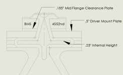
This latest attempt has been the only one thus far, I've been tweaking it as I go. 1/4" mdf for the plates which measures about .225 actual thickness. It's pretty smooth but there are a few spots at the bends inside that open a bit more than the .225 thickness, maybe .05 or so that could be addressed. The top inch or so on the left side of each Paraline got a bit "lazy"
. My template was off and I didn't realize it till I was done. Probably goofs up the path lengths a bit. They're definitely not perfect! The "open eye" layers got a 45° chamfer around the perimeter when I cut them out, effectively adding reflectors in the internal bends. I'm not sure if that was necessary when the sound is constrained in the device but it can't hurt.Looking at my 4552s I measure about 27° included angle in the driver exit. I got to looking at my tools and I've got a step drill that has about a 30° total angle on it. I'm off Friday and a project sounds fun. Talking snow tomorrow....... It's almost May!
Hopefully by Sunday I'll have both Paralines modified to have a reflector running nearly to the phase plug, following the driver exit angle and beginning the 1/4" internal height in the comp driver itself. It's going to be difficult to get the driver lined up over the reflector properly..... We'll see. If I have to I'll pull the back chamber/diaphragm assembly and mount the magnets first so I can see down the throat. I've got a cad drawing I'll post up later today showing what I'm up to.
Member
Joined 2003
Me too...I like acoustic solutions to acoustic problems!
Me too. Even if Danley's Paralines don't prove useful for hifi and HT, I still enjoy investigating how he looks at sound reproduction. He is one of the most creative minds in the field and luckily he is willing to hang out with us and be open about his perspective.
Geddes is another great mind and typically a big fan of acoustic solutions. There is nothing wrong with being a skeptic though. All good ideas need skeptics.
There is nothing wrong with being a skeptic though. All good ideas need skeptics.
You have to understand that most "innovations" simply don't pan out. This is true for concepts that I have had as well as what others have done. I have found that its best to get to the problems as fast as possible as that saves a lot of time spent chasing ineffective ideas. We are hard wired to be optimistic about new ideas, but pessimism is usually the more efficient approach.
You have to understand that most "innovations" simply don't pan out. This is true for concepts that I have had as well as what others have done. I have found that its best to get to the problems as fast as possible as that saves a lot of time spent chasing ineffective ideas. We are hard wired to be optimistic about new ideas, but pessimism is usually the more efficient approach.
I'm hardwired for pessimism, but I honestly don't have the chops to be skeptical on the level that many of you do. I was being straightforward in saying good ideas, as much as bad ones, need skeptics. Aggressive, petulant skeptics in fact.
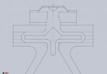
For reference here's how it's currently setup. This is what was used for the last set of measurements I showed.
Yep, that gap is definitely larger than the prescribed 1/3 or 1/4 wl limit which, in my lay mind could be the source of the HF response anomalies...or it might be meaningless.
Member
Joined 2003
Hi Earl, all
Earl if you follow the drawing in fig 2, you might notice something reminiscent of an old AT&T microwave horn.
Patent US8259981 - Horn-loaded acoustic line source - Google Patents
like these here;
http://www.engineeringradio.us/blog...09/07/western-electric-microwave-antennas.jpg
The AT&T antenna was the inspiration except that reflection based systems require the reflector be very large with respect to the wavelength if one wants a constant behavior over any bandwidth. My idea was to use a path length correction along that line.
In Fig2B in the patent, picture that to the degree the driver exit is acoustically small, a pressure radiates away trapped between two layers at a dimension that is no larger than about ¼ wl at the highest frequency of interest. While trapped between two layers in one plane, in the other it is expanding.
While one side of this passageway is solid, the other is solid but also has a slot cut in it, a slot the same width as the slot thickness Fig2C.
That slot’s outer extent is also where the passageway in layer 2B ends so that the pressure flows around that (acoustically small) corner.
Layer c is typically thin, less than the width of the slot fwiw.
On the other side of layer 2C is the exit layer 2D.
The exit layer is also a narrow passageway in the thickness dimension.
Now, if one made the correction slot and layer shapes a straight line instead of curved, the exit radiation angle is the same as the incoming angle (like a flat mirror does with light). But if the slot is curved, one can create a new exit angle.
Now, if you examine Fig 4, you can see the idea extended to be fully symmetric. Now as the sound enters hole 116, it must radiate outward and unlike the earlier version, there are no horn walls which could support higher order modes, it is free radial expansion at the speed of sound and the thickness dimension too small to support them..
Here path D1 is the shortest and here is where is passes through the correction slot C first. In the exit layer, the sound progresses towards and exits from the center slot.
To produce a flat wavefront , the paths A1+A2 and so on are all equal lengths. A “real” line source (no curvature) has too many problems related to it’s size so usually they have some curvature assigned to them.
Like any horn, there are acoustic dimensions which govern how sound behaves, this is not free of those constraints but the device has proven very useful when one doesn’t want a large deep horn or if you want to make a much more uniform array using individual boxes..
A BIG problem with a simple array of sources is that while they do (or can) produce the radiation of a large source, all of those sources still radiate individually as well and so while line sources (as used) are purported to have a high directivity, they do not compared to a modestly large horn.
Consider how one might design a normal output 5 foot tall horn which HAD to have pattern control to a low frequency (say 250Hz) AND say a 10 degree vertical by 50 degree horizontal pattern and NOT have pattern flip?
One way involves a VERY deep horn but by using the Paraline, one can do it with one driver and only a few inches of depth if you want.
For the diy’rs, I mentioned open wood pores being bad, if you make them out of aluminum or plates, keep in mind there are also little gaps. In my first few made of wood, I poured some polyurethane into is and rotated it around to seal off all the nooks and crannies, those may be good on E-muffins but not here.
Also, while you can make one that works as intended, I would not start that project until you have a good handle on how not to have pattern flip. The more asymmetric you make the pattern, the more problematic this unappreciated problem becomes.
If you have ever seen an old EV t-35 mounted “the wrong way” (up and down), that is the right way, based on how that horn actually radiates below 10KHz and that because of pattern flip.
In other words, if your keen to make one of my inventions, go for a Synergy horn, it is the simplest, is subjectively different and has the largest number of DIY’rs that have figured it out, a few have found the way to eliminate the crossovers “all pass” phase shift as well but with an active crossover, that is much easier.
Earl I remember telling you I would take an SH-50 out and do the measurements you needed to look at them that way. I have not done that and didn’t remember the last time I was outside doing polar’s last summer.
I normally don’t do them beyond the curiosity or troubleshooting stage and at that using the TEF machine and turntable. For product data, we have Pat Browns company do the full spherical measurements (too many points on a sphere, way too hard for me as I don’t have a giant space or a robot to move the loudspeaker).
Sebastian the fellow who did the DDT programs on our web site may be able to take the 5 degree raw data Pat has taken and plot that as a map in the H or V plane vs frequency.
I will ask if that can be put on the task list as I agree it would be interesting to see how they look vs hifi speakers using the Horizontal & Vertical plane map view.
Got to run, time to change another sump pump (we got nearly 2X April's normal rain, night before last).
Best,
Tom
Here's the drawing.......clear as mud? I'm not one for fancy illustrations.
The .185 plate allows the CD to sit above the mid drivers' mounting flange, it's tight. I can take a pic if that doesn't make any sense.
Very cool drawings.
I've learned so much from mocking things up in Xara.
One thing -
Be careful about the reflectors in the correction slot.
I believe that one of the reasons that my 'Stargate' measures well is that it has fewer reflectors. I'm not an expert on fluid dynamics, but from what I know I believe that the transition in the correction slot is likely the spot where turbulence could create issues.
Basically, if you make the reflectors too big you create a 'choke point' which may be turbulent. Make them too small and you get diffraction at a lower and lower frequency. (The correction slot WILL diffract; the trick is to push the diffraction to the highest frequency possible. It's the reason I use 0.20" wood for mine. I've considered using clear plexiglass as that would make everything a lot easier.)
Also, if you guys aren't using a plexiglass mounting plate, like Geddes does, RUN don't walk to your nearest Tap Plastics and get on that! Plexiglass makes EVERYTHING so much easier.
- Home
- Loudspeakers
- Multi-Way
- Square Pegs