This is branched off from the western-electric-1928-how-far-have-we-come-last-100-years thread.
This part is about the reverse engineering, design, and possible DIY of the WE 555 driver. Also considered are related and unrelated drivers, and commercial clones of the 555.
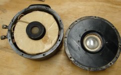
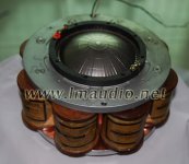
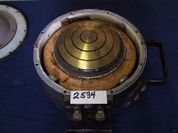
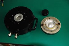
To kick it off here are some random pix from around the web of the 555 and related products:
This part is about the reverse engineering, design, and possible DIY of the WE 555 driver. Also considered are related and unrelated drivers, and commercial clones of the 555.
To kick it off here are some random pix from around the web of the 555 and related products:
Attachments
I would like to make computer model the physical driver if I could find some accurate measurements.
Here is a sweep of the 555.
Western Electric 555 driver SN 49771 sweep test - YouTube
Here is a sweep of the 555.
Western Electric 555 driver SN 49771 sweep test - YouTube
actually the static pictures show a lot about the design and construction. You could build one with just those pictures, if you had some background knowledge.
The real problem in building one DIY is not the dimensions or the basic design, since the basic design is in the patent... something to think about here.
_-_-bear
fwiw the 3rd picture is a WE but not a 555...
The real problem in building one DIY is not the dimensions or the basic design, since the basic design is in the patent... something to think about here.
_-_-bear
fwiw the 3rd picture is a WE but not a 555...
The real problem in building one DIY is not the dimensions or the basic design, since the basic design is in the patent... something to think about here.
The diaphragm looks like the bottom of a pop can, apart from the tangential ribs for a surround. Perhaps a thin flat rubber disk, or even a standard spider, could serve as a surround. Use the pop can sides as a voice coil former.
The real problem in building one DIY is not the dimensions or the basic design, since the basic design is in the patent... something to think about here.
_-_-bear
Are you sure about that?
I'm not sure what you are going to gain without hands on experimentation.
I think the first and fourth are 555 and the other 2 are more modern. If you want to get to the sound of a 15a you need to get the operating range down to the point of being useful in a full range horn. Low resonance and high Excursion will be the greatest challenge.
Line drawings of the 555 show the reversing sphere cross section and simple phase plug, like the first and fourth picture.
Line drawings of the 555 show the reversing sphere cross section and simple phase plug, like the first and fourth picture.
the second one is a Line Magnetics driver, probably a clone of the later WE594 (do I have the number right?) and the third one is a WE594 showing the phase plug and the field coil.
Afaik, almost all the compression drivers operate below their fundamental resonance frequency when loaded with a horn. I find that a bit confusing, but iirc this is correct...
I be no expert on this.
_-_-bear
Afaik, almost all the compression drivers operate below their fundamental resonance frequency when loaded with a horn. I find that a bit confusing, but iirc this is correct...
I be no expert on this.
_-_-bear
Afaik, almost all the compression drivers operate below their fundamental resonance frequency when loaded with a horn. I find that a bit confusing, but iirc this is correct...
_-_-bear
Yes, I believe you are correct on this. The resonance is revealed in the impedance curve and can be more in the middle of the band.
We are fairly conditioned by our understanding of direct radiators, while horns are different. With a horn the air load is flat (for an ideal horn) rather than rising as it does with a small piston, and constant velocity gives flat radiated power.
Getting wider range out of a horn system still requires more than just a larger horn. Higher excursion with low distortion is still required from the compression driver.
David
Ron, I suspect the stiffness and the mass of the surround is an important design criterion?
Playing with my Hornresp model of a WE555 on a 15ft. expo flare, I noticed something interesting about the diaphragm suspension compliance. Once when I mistakenly had the compliance set two orders of magnitude too high (too soft), I found that it made hardly any difference at all in the system response.
The air load entirely swamps the effect of the diaphragm compliance up to a certain break point.
Because it operates below resonance, suspension has a more critical role in compression driver than direct radiators i believe.
If we look at the equivalent electrical circuit we can see that below resonance the driver is controlled by its suspension system. In my mind the best solution is to use mylar. It's also pretty easy to source Ti diaphragms with mylar surround.
Because the diaphragm is very hard to make at DIY level, i think design work should start from here. From available dia to work down to motor structure which can be made accordingly to the WE555.
Designing a phase plug for an available dia will take most of the time. I have found Axidriver to be a very useful tool. Example of a diaphragm/phase plug assembly below:

Parameters that need consideration once a diaphragm diameter is considered, are dome height and compression chamber height.
Although PP structure has evolved ( to better or worse results) i find Henricksen's paper a good start:
Henricksen_1978_Tangerine_PP.pdf
If we look at the equivalent electrical circuit we can see that below resonance the driver is controlled by its suspension system. In my mind the best solution is to use mylar. It's also pretty easy to source Ti diaphragms with mylar surround.
Because the diaphragm is very hard to make at DIY level, i think design work should start from here. From available dia to work down to motor structure which can be made accordingly to the WE555.
Designing a phase plug for an available dia will take most of the time. I have found Axidriver to be a very useful tool. Example of a diaphragm/phase plug assembly below:
Parameters that need consideration once a diaphragm diameter is considered, are dome height and compression chamber height.
Although PP structure has evolved ( to better or worse results
) i find Henricksen's paper a good start:Henricksen_1978_Tangerine_PP.pdf

- Status
- This old topic is closed. If you want to reopen this topic, contact a moderator using the "Report Post" button.
- Home
- Loudspeakers
- Multi-Way
- Western Electric 1928 - WE 555 Dissect, Design, DIY??