Correct, when it comes to a cardioid response the boxless/muffler approach produces similar results to the box with side holes that is stuffed with absorbing material.
I was thrown off by the term "resistive vent" because that is used in an Aperiodic Loudspeaker Enclosure Design for bass tuning. With resistive ports on the side of the box an aperiodic enclosure should theoretically produce some type of cardioid response. Unfortunately, I'm not familiar with any research that specifies how different parameters can be optimized to arrive at a desired response.
Oh, I see. Right, resistive ports might be a more appropriate name, although they do the same thing but with different purposes. Considering the muffler terminology I would actually be tempted to call them sidepipes (referring to automotive terminology, in case you're not in to that kind of thing), but that sounds like bass reflex boxes instead... Many uses for holes in boxes; wonder what one can learn from models of the other ones?
Olsen [1] is often cited in this context, as is Holmes [2]. Holmes is more to the point in this context and likely worth digging into. I have not, yet, so can't tell how specific he gets.
[1] H. F. Olsen, Gradient Loudspeakers, JAES 21, 89, 1973
[2] T. J. Holmes, The "Acoustic Resistance Box" -- A Fresh Look at an Old Principle, JAES 34, 981, 1986
Not following your logic here. I think you are saying all would be well if the floor reflections have flat response, or that if speakers send messy response towards the floor that proves it must be inconsequential. That isn't true. Floor and ceiling bounce energy, no matter what the spectrum, will arrive at the ear just enough delayed to give very significant comb filtering.
The issue is one of psychoacoustics. We are inundated with reflections from all directions. If they come from the sides our binaural hearing lets us separate them very well from the frontal sound. We perceive them as added spaciousness or image spread. Anything that arrives on the median plane (the plane halfway between the two ears) we will have a hard time seperating out. It will be combined with the direct sound as a nonflat, comb filtered composite.
Vertical directivity of any form is useful. Lateral reflections, if sufficiently delayed, are pleasant and add spaciousness. Toole writes a lot about this, you should read his book.
D'Appolitos should be vertical!
David S.
I can't resist to comment that it would be cool with a symmetric-pair setup á la Keele to control vertical directivity, combined with the side ports we are discussing here to control horizontal directivity!
")
Oh, I see. Right, resistive ports might be a more appropriate name, although they do the same thing but with different purposes. Considering the muffler terminology I would actually be tempted to call them sidepipes (referring to automotive terminology, in case you're not in to that kind of thing), but that sounds like bass reflex boxes instead... Many uses for holes in boxes; wonder what one can learn from models of the other ones?
Olsen [1] is often cited in this context, as is Holmes [2]. Holmes is more to the point in this context and likely worth digging into. I have not, yet, so can't tell how specific he gets.
[1] H. F. Olsen, Gradient Loudspeakers, JAES 21, 89, 1973
[2] T. J. Holmes, The "Acoustic Resistance Box" -- A Fresh Look at an Old Principle, JAES 34, 981, 1986
Another good paper is: Unidirectionally Radiating Loudspeakers by W. H. Idling from the 1972 AES Munich Convention.
He shows some pretty decent response with 10 to 13 dB rejection in the backwards direction. A response curve in front of a rear wall shows nicely improved response compared to a conventional speaker.
David
Member
Joined 2003
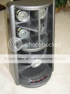
Don't know how much help this will be, but this is the bottom of a 3-way dipole/cardioid/monopole WG from 5-6 years ago. The back of the baffle was a semi-circular piece of 1" wool felt captured by heavy wire mesh inside and out. I used the felt to transition from a dipole (at ~DC), through ~cardioid mids, to ~monopole at the upper XO of around 1.2k.
Another good paper is: Unidirectionally Radiating Loudspeakers by W. H. Idling from the 1972 AES Munich Convention.
He shows some pretty decent response with 10 to 13 dB rejection in the backwards direction. A response curve in front of a rear wall shows nicely improved response compared to a conventional speaker.
David
Thanks for the ref, David, that sounds like a paper I might consider worth cashing out for. In fact, googling for it brought me to a patent by Idling in which I found a picture that made me reconsider a test bed for my little 3.5-ers:

a slotted pipe, with larger size, similarly slotted pipe (or rings) slid on top. Turn the rings to adjust size of the vents. Could make for a fun looking array, actually.
Now I just have to learn how to tame pipe resonances...I am pretty sure I've seen this arrangement mentioned somewhere before, wonder where that was...
Don't know how much help this will be, but this is the bottom of a 3-way dipole/cardioid/monopole WG from 5-6 years ago. The back of the baffle was a semi-circular piece of 1" wool felt captured by heavy wire mesh inside and out. I used the felt to transition from a dipole (at ~DC), through ~cardioid mids, to ~monopole at the upper XO of around 1.2k.
That's a very good looking speaker Paul! I for one would be very interested in hearing more about it (like what the results were, your tuning experience and if there were particular issues and problems), but I feel like I'm starting to hijack Boris' thread (sorry Boris)..
Member
Joined 2009
Thanks for the ref, David, that sounds like a paper I might consider worth cashing out for.
http://www.ee.ic.ac.uk/naylor/LineSourceLoudspeakers/iding.pdf
No problem. I'm interested in learning more about it as well.That's a very good looking speaker Paul! I for one would be very interested in hearing more about it (like what the results were, your tuning experience and if there were particular issues and problems), but I feel like I'm starting to hijack Boris' thread (sorry Boris)..
Yep, I found it as well.
Iding used copper mesh on side slits of a line array. And his response looks darn good to my untrained eyes.Member
Joined 2009
We may not perceive vertical reflections well for imaging but they'll cause colouration, as will the horizontal reflections. Horizontal reflections usually are treated in a constant directivity design, by way of the directivity itself.
I don't agree that the ceiling reflection will be easy to equalise.
Not following your logic here. I think you are saying all would be well if the floor reflections have flat response, or that if speakers send messy response towards the floor that proves it must be inconsequential. That isn't true. Floor and ceiling bounce energy, no matter what the spectrum, will arrive at the ear just enough delayed to give very significant comb filtering.
The issue is one of psychoacoustics. We are inundated with reflections from all directions. If they come from the sides our binaural hearing lets us separate them very well from the frontal sound. We perceive them as added spaciousness or image spread. Anything that arrives on the median plane (the plane halfway between the two ears) we will have a hard time seperating out. It will be combined with the direct sound as a nonflat, comb filtered composite.
Vertical directivity of any form is useful. Lateral reflections, if sufficiently delayed, are pleasant and add spaciousness. Toole writes a lot about this, you should read his book.
D'Appolitos should be vertical!
David S.
Dave and Allen,
Thank for patiently explaining the issue! I'm grateful for your input.
At first I was worried about the lobe in the vertical response caused by the crossover between the midwoofer and the tweeter. Now I'm starting to think that the woofer array might be causing more trouble than I hoped to solve. I plan to use it below 500Hz but I could move the crossover lower if that will help.
Aside from the obvious WWTMWW arrangement, what would you suggest for improving the vertical response?
A good MTM geometry will give a reasonable amount of vertical directivity. Joining it with a woofer placed at floor level can allow a crossover, for the woofer, below the first null, and a crossover, for the mids, above their first primary null. This is much like the Allison speakers.
David
David
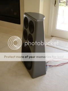
Hey boris, any more test/progress... your first design looks like the Amphion Krypton 3, as far as your flow resistive pattern, was wondering what the theory is behind it, I was first just interested in getting cardioid in the bass but now thinking of going to the midrange also. I just made a little testbox with a single mid and poked some holes in it just to see what is what, first started with holes of .25" one inch appart, didn't really get good results (all testing done by ear, I have a measurement setup but it's very easy to tell if something is headed in the right direction or not) anyway had to to up to .5 holes and 80% stuffed to really get anything working, will begin measurements today.
Member
Joined 2009
Hey boris, any more test/progress... your first design looks like the Amphion Krypton 3, as far as your flow resistive pattern, was wondering what the theory is behind it, I was first just interested in getting cardioid in the bass but now thinking of going to the midrange also. I just made a little testbox with a single mid and poked some holes in it just to see what is what, first started with holes of .25" one inch appart, didn't really get good results (all testing done by ear, I have a measurement setup but it's very easy to tell if something is headed in the right direction or not) anyway had to to up to .5 holes and 80% stuffed to really get anything working, will begin measurements today.
I don't have a solid grasp on the theory myself. One major point is that cardioid resulting from vents on the sides of the cabinet is not the same as cardioid from a U-frame.
NaO U-frame
In this study of the U-Frame design, John Kreslosvky finds that the back wave develops a resonance above the dipole peak. Alternatively, side vents designs have the advantage of a consistent polar response at the expense of sensitivity.
Often I see mentioned that the total area of the vent holes exceeds the area of the woofer. I don't know how that affects the response but 80% of Sd on each side (x2) seems to be common. I don't know the effect of the hole pattern either, I copied it from the Amphion Krypton 3 and Kimmo Saunisto's designs.
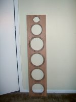
I'm excited to see your measurements. I will hopefully have something soon myself. I am going for an open structure with driver mufflers instead of a leaky box. I got the drivers and I cut the front baffle and now I'm thinking of how to execute the driver magnet mounting. Ideally I would like to use bamboo plywood but I wasn't able to find any in my area. The most attractive alternative at my local Home Depot was this wooden composite board. It is intended for making steps and it is very heavy.
----
"Some Krypton 3 comments from people who know what they are talking about: "Amphion at $ 19.9.K is a bargain""


Attachments
Member
Joined 2009
a bit of theory - feel free to make corrections and contribute
The basic concept behind Open Baffle is that there are 2 waves going out in space, one from the front and another from the rear of the driver. They are at equal power but opposite polarity so they will act to cancel each other out. The cancellation is not complete but partial and depends on the wavelength and the distance a wave must travel around the baffle from the driver center at the front to the back. A naked driver with no baffle represents the classic dipole model - no cancellations occur at high frequencies when the wavelength is shorter than the driver cone; as soon as the wavelength grows enough for the driver to begin radiating in >2pi space, the front and rear wave "meet" and we begin to encounter cancellations. The amount of cancellation is proportional to the amount of energy that is able to "wrap around" the baffle and generally follows a -6dB/octave slope. (comb filter nulls will develop in higher frequencies on an open circular baffle but their effect can be minimized with a rectangular baffle)
In a U-Frame configuration the wings of the baffle delay at what wavelength the rear wave can "wrap around" effectively shifting the geometry of the dipole cancellation towards the back. Since the rear radiation is contained in 2pi space for lower in frequency than the front an irregularity in the FR will form at the rear.
On a flat open baffle when the rear wave is partially absorbed the dipole cancellation will be shifted to the rear and form a cardioid-type response as well. But in this case it will be the result of different power at the front and rear contrary to the case of different distances(phase) as it is with a U-Frame cardioid. The rear absorption method will have the advantage of more consistent power response over a U-Frame at the expense of sensitivity.
I am not entirely done with the theory myself, but at a glance I can not see why you would assign different physical reasons to the effect in the U-frame and open baffle cases?
In the case of side ports at least, I tend to think delay rather than power damping.
Edit: And in that case you will get a net result by the superposition of the sub-patterns caused by each port; so equations valid for the case of a rear port (which I compare the u-frame case) can not be used as are.
Last edited:
Member
Joined 2009
I am not entirely done with the theory myself, but at a glance I can not see why you would assign different physical reasons to the effect in the U-frame and open baffle cases?
In the case of side ports at least, I tend to think delay rather than power damping.
Edit: And in that case you will get a net result by the superposition of the sub-patterns caused by each port; so equations valid for the case of a rear port (which I compare the u-frame case) can not be used as are.
Because in a classic dipole the front and rear wave (at the center axis) will have the exact same Frequency Response and the Phase of both will generally track together with a 180deg difference for the frequency range of the driver.
A U-Frame will keep a stable cardioid response only below the dipole peak where the FR and phase will track together. The rear wave will of course be attenuated compared to the front one but the traces should track together analogous to the phase. Above the dipole peak the front and rear phase will seize to track together and resonances will develop in the rear wave response.
I don't exclude the possibility to be wrong about this. But I prefer to approach the theory of a box with leaky side panels as a dipole with an attenuated rear wave rather than a U-Frame with an offset rear opening. I expect the FR and phase to track together even above the dipole peak, especially for supercardioid.
U-Frame theory
NaO U-frame
DIY-dipole-1
Measurements from builders of cardioid leaky boxes
http://www.diyaudio.com/forums/multi-way/192737-2-way-waveguide-cardioid-like.html
Cardioid bass
http://www.diyaudio.com/forums/multi-way/142691-adventures-cardioid.html
I don't exclude the possibility that you are right about this, but I was under the distinct understanding that there would be the equivalent of a dipole peak in a side port system as well. And that you would not be able to obtain a cardioid response above this threshold.
In the u-frame case one discusses the acoustic separation of the two out-of-phase monopoles, and must delay the rear source according to this separation. In the side port case, a similar separation exists due to the baffle and position of the ports down the side of the cabinet. A similar delay is then necessary?
Having said this, I admit to having no intuition for the result of two non-delayed sources of differing intensity. So I'm not sure.
Edit: By the way, I always interpreted the bettered result seen without baffle in the "adventures in cardioid"-thread as related to what we are discussing here.
Last edited:
A quote from Holmes (this is all he writes about side ports,
unfortunatelly):
unfortunatelly):
1.3 Position of Resistor Vent--Rear versus Both Sides
The effect of dividing up the resistive vent area-
into a pair of symmetrically placed side vents, for
instance--can be analyzed by treating the system as a
set of subsystems, each with its own volume velocity
and axial direction. Each subpattern can then be derived
independently.
Overlaying these subpatterns, with their axes intersecting
at front center, will now yield the net pattern, always with
a beta value lower than those of the subpatterns.
Member
Joined 2009
In the u-frame case one discusses the acoustic separation of the two out-of-phase monopoles, and must delay the rear source according to this separation. In the side port case, a similar separation exists due to the baffle and position of the ports down the side of the cabinet. A similar delay is then necessary?
The way I understand the mathematical abstraction is that there is NO delay in the dipole model between the two out-of-phase sources. There is a delay in the U-Frame model and it is there to represent that the 2 out-of-phase sources begin to radiate in >2pi space at different wavelengths.
I don't think that there would be a delay in the cardioid model of a leaky box with side vents. I'm under the impression that the front and rear wave will continue tracking together in phase at 180degrees apart. There might be some delay caused by the low-pass function of the box but I assume that it will be minimal and not relevant.
Attachments
The way I understand the mathematical abstraction is that there is NO delay in the dipole model between the two out-of-phase sources. There is a delay in the U-Frame model and it is there to represent that the 2 out-of-phase sources begin to radiate in >2pi space at different wavelengths.
I don't think that there would be a delay in the cardioid model of a leaky box with side vents. I'm under the impression that the front and rear wave will continue tracking together in phase at 180degrees apart. There might be some delay caused by the low-pass function of the box but I assume that it will be minimal and not relevant.
What I see in those figures is exactly what I am trying to argue: If you have no delay, you get a dipole. Add delay, get cardioid. In my mind it is all about how the radiation sources (the point where the waves exit the box, if we put it that way) interfere. To have two monopole sources sum to a cardioid pattern, they must be phase-inverted, and the rear one delayed by T=D/c, where D is the separation. A different delay gives a different pattern (0 gives dipole, D/(2c), roughly, gives supercardioid).
Edit: By the way, the relation between the separation and the caridoid-izable wavelengths is seen in the right figure as well. You need to keep the separation such that you are in the roughly linear region in the response plot.
Last edited:
- Status
- This old topic is closed. If you want to reopen this topic, contact a moderator using the "Report Post" button.
- Home
- Loudspeakers
- Multi-Way
- Waveguie and Cardioid on a Slim Baffle