Member
Joined 2009
What I see in those figures is exactly what I am trying to argue: If you have no delay, you get a dipole. Add delay, get cardioid. In my mind it is all about how the radiation sources (the point where the waves exit the box, if we put it that way) interfere. To have two monopole sources sum to a cardioid pattern, they must be phase-inverted, and the rear one delayed by T=D/c, where D is the separation. A different delay gives a different pattern (0 gives dipole, D/(2c), roughly, gives supercardioid).
Edit: By the way, the relation between the separation and the caridoid-izable wavelengths is seen in the right figure as well. You need to keep the separation such that you are in the roughly linear region in the response plot.
Right. I'm going a step further to say that a cardioid might also be described by a 3rd model - no delay, 2 polar opposite sources one of which is attenuated. I'm suggesting that the difference of the sources' powers and the delay in this abstraction might be interchangeable. The practical implication of this would be that the phase distance of the 2 sources will remain the same in the 3rd model.
If I am wrong and it can be shown that leaky boxes and U-Frames act the same then I will abandon the original idea. As far as I'm concerned U-Frames are easier to build and will allow me to better tune the low end.
Got it, thank's for the patient explanation.
Very interesting project that in many ways are similar to mine (http://www.diyaudio.com/forums/multi-way/193717-build-thread-obeos.html). Although nothing has been written on my thread for a long time, the project is far from dead. Also we have a Norwegian forum project ongoing utilizing cardioid midrange.
I would like to discuss if it is feasible to apply a damped U-baffle for the midrange. The idea is to combine the dispersion of the damped U-baffle with the natural dispersion of the driver. Simplified maths says yes, but I encounter some problems when measuring it indoor. I have to add that I haven't been able to measure outdoor, which is the next thing on the menu when the weather allows for it.
In basic we want to make the U-baffle with the dipole peak entering the frequency band above the point where the baffle/driver itself starts beaming. Adding the selected damping material should attenuate the rear energy and consequently the dipole peak will be supressed. This way "high efficiency" cardioid dispersion may be achieved over a wider bandwidth, letting the driver control the dispersion in high frequencies and the U-baffle in the lower.
Could it work?
By the way, it would be very nice if JohnK could share his experience and opinions in this thread.
Very interesting project that in many ways are similar to mine (http://www.diyaudio.com/forums/multi-way/193717-build-thread-obeos.html). Although nothing has been written on my thread for a long time, the project is far from dead. Also we have a Norwegian forum project ongoing utilizing cardioid midrange.
I would like to discuss if it is feasible to apply a damped U-baffle for the midrange. The idea is to combine the dispersion of the damped U-baffle with the natural dispersion of the driver. Simplified maths says yes, but I encounter some problems when measuring it indoor. I have to add that I haven't been able to measure outdoor, which is the next thing on the menu when the weather allows for it.
In basic we want to make the U-baffle with the dipole peak entering the frequency band above the point where the baffle/driver itself starts beaming. Adding the selected damping material should attenuate the rear energy and consequently the dipole peak will be supressed. This way "high efficiency" cardioid dispersion may be achieved over a wider bandwidth, letting the driver control the dispersion in high frequencies and the U-baffle in the lower.
Could it work?
By the way, it would be very nice if JohnK could share his experience and opinions in this thread.
Could you link to the thread on the norwegian forum? I might be interested to check it out since I want to do the same thing.
")
Personally I think the difficult part is to find a material/port combination which has the correct resistivity, and is such that the resistivity does not change over the relevant frequency range and SPL. Linkwitz explains it here: Frontiers
The forum thread in question: AVforum.no - Dynamiker's forslag til Forumprosjektet 2012. Your contribution will be highly appreciated
Thanks, I'll read the Linkwitz articles thoroughly to see if there is a solution to be found between the lines.
Thanks, I'll read the Linkwitz articles thoroughly to see if there is a solution to be found between the lines.
Member
Joined 2009
I would like to discuss if it is feasible to apply a damped U-baffle for the midrange. The idea is to combine the dispersion of the damped U-baffle with the natural dispersion of the driver. Simplified maths says yes, but I encounter some problems when measuring it indoor. I have to add that I haven't been able to measure outdoor, which is the next thing on the menu when the weather allows for it.
In basic we want to make the U-baffle with the dipole peak entering the frequency band above the point where the baffle/driver itself starts beaming. Adding the selected damping material should attenuate the rear energy and consequently the dipole peak will be supressed. This way "high efficiency" cardioid dispersion may be achieved over a wider bandwidth, letting the driver control the dispersion in high frequencies and the U-baffle in the lower.
Could it work?
By the way, it would be very nice if JohnK could share his experience and opinions in this thread.
From your description it sounds like you are trying to do what JohnK was experimenting with. When using a U-Frame I believe the front wave can be made to transition smoothly from beaming into cardioid but the rear wave will be a problem. If you are interested in a good rear wave I might be wrong I don't believe it's doable with a U-Frame regardless of damping.
Member
Joined 2009
Thanks Boris. Do you know if there's an article to read about JohnK's attempt?
NaO U-frame
This is the article I'm referring to. Although the damped response ends up looking OK, JohnK chooses to use the U-Frame only below the dipole peak. I do hope that he joins this thread and help us understand this better.
Member
Joined 2009
some progress
I became inpatient and put together a crude structure. I had some promising results and many setbacks. I finally have a prototype and can begin testing but it's become obvious that I need to rethink many of my original ideas for the enclosure.


Stability is a major concern with such a tall, slim and heavy structure, especially when it's placed on carpet. I have to construct wide feet with spikes and I worry that they might have to spread more than I anticipated.
I realised the way I was planning to support the woofers at the rear was flawed and I need to come up with a different strategy. I was going to use tension bolts that pull the basket but supporting the magnet itself will be more effective. Interestingly, vibration doesn't seem to be an issue at moderate listening levels although I haven't really investigated that area.
I had a problem with the bass equalization that took me a few days to figure out. It was caused by the kx-Project - my DSP platform. The WaveIn stream had no headroom and applying bass boost filters sounded horrible. That was a strange issue because the ASIO stream, which I usually use is attenuated by 12dB.
When that was finally solved I took some indoor measurements. They are mostly to figure out the crossover for the tweeter and the midwoofer. There is also some very crude off-axis data from the midwoofer. I couldn't get good measurements between 90-160 degrees but it looks like the response is forming a supercardioid.
Tweeter and Midwoofer with a quick crossover. These are very crude indoor measurements, I will try to get something better. 0degrees - red, 60 - Blue, 90 - Green, 160 - Gray, 180 - Black.

I focused most of my attention on the TM crossover. This is showing a Le Cleac'h at 1400Hz.

I became inpatient and put together a crude structure. I had some promising results and many setbacks. I finally have a prototype and can begin testing but it's become obvious that I need to rethink many of my original ideas for the enclosure.
Stability is a major concern with such a tall, slim and heavy structure, especially when it's placed on carpet. I have to construct wide feet with spikes and I worry that they might have to spread more than I anticipated.
I realised the way I was planning to support the woofers at the rear was flawed and I need to come up with a different strategy. I was going to use tension bolts that pull the basket but supporting the magnet itself will be more effective. Interestingly, vibration doesn't seem to be an issue at moderate listening levels although I haven't really investigated that area.
I had a problem with the bass equalization that took me a few days to figure out. It was caused by the kx-Project - my DSP platform. The WaveIn stream had no headroom and applying bass boost filters sounded horrible. That was a strange issue because the ASIO stream, which I usually use is attenuated by 12dB.
When that was finally solved I took some indoor measurements. They are mostly to figure out the crossover for the tweeter and the midwoofer. There is also some very crude off-axis data from the midwoofer. I couldn't get good measurements between 90-160 degrees but it looks like the response is forming a supercardioid.
Tweeter and Midwoofer with a quick crossover. These are very crude indoor measurements, I will try to get something better. 0degrees - red, 60 - Blue, 90 - Green, 160 - Gray, 180 - Black.
I focused most of my attention on the TM crossover. This is showing a Le Cleac'h at 1400Hz.
Say boris ... since you're intention is mag mounting, think from there forward.
Long pole behind drivers supported at ground level by a tripod .. one long (pole) leg straight back two shorter below baffle location perhaps? ( should look like a birds foot in plan view) Brackets/circular clamps allowing the magnet mounting/spacing to the vertical pole and flat "straps" attached to vertical pole (rear and wrapping forward) to support the baffle. Straps could also act as a form for your "muffler(s)"?
Should be pretty solid I'd think. Measurements don't look half bad either. "thumbup"
Last edited:
Member
Joined 2009
Say boris ... since you're intention is mag mounting, think from there forward.
Long pole behind drivers supported at ground level by a tripod .. one long (pole) leg straight back two shorter below baffle location perhaps? ( should look like a birds foot in plan view) Brackets/circular clamps allowing the magnet mounting/spacing to the vertical pole and flat "straps" attached to vertical pole (rear and wrapping forward) to support the baffle. Straps could also act as a form for your "muffler(s)"?
Should be pretty solid I'd think. Measurements don't look half bad either. "thumbup"
Thank you!
I plan to look at pre-cut furniture legs at the local Home Depot. An X shape will be most stable but if I don't find anything I like I will build an H shape one. I already ordered nice spike feet.
My initial idea was to mount another wooden board at the back perpendicularly to the baffle. I had trouble making adequate cutouts for the drivers so I abandoned the idea. It is probably the best solution, I just need to get more creative about how to get it to work.
I can use swivel-head bolts to press against the magnet and that will hold it solid. It's easier to do it from the back of the magnet but doing it from the sides can give it more more sideways support. I'm not sure which direction is more important although I feel like either way the driver will have ample support.
An externally hosted image should be here but it was not working when we last tested it.
Member
Joined 2009
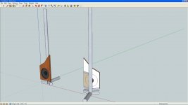
Did a quick sketch of what I was trying to convey.
Nice! I was picturing something very similar from your description. Somebody actually posted a similar structure today. My trouble is that I can't do accurate cuts. The baffle I'm using right now is very heavy it's probably not a good idea to suspend it from a support beam.
http://www.diyaudio.com/forums/subwoofers/213323-ob-elegance-3.html#post3036895
Member
Joined 2009
more indoor measurements
I did some work on the crossover.
The tweeter-to-mid is a Le Cleac'h phase linear 3rd order at 1400Hz. The mid-to-woofers is a bit strange. It's technically 1st order. The mid has no highpass filter but the open baffle naturally drops the response at around 500Hz with a 6dB/oct slope. The same effect acts on the woofers as well and to compensate I put a 1st order lowpass at 125Hz and boosted their level by 12dB. Interestingly, the woofer response drops off very quickly above 500Hz. (I later took care of the woofer bump at 1500Hz)

I did this crossover mainly because I wanted linear phase and I haven't been able to combine 2 Le Cleac'h in the same system yet. I'm not sure if the problem is that there must be some distance between them or I messed up the routing. Although unusual this measures and sounds pretty good.

The resulting phase is very linear throughout the critical 300-3000Hz region. The peak at the top is characteristic of my sound card and hopefully will not be there if I use another platform like miniDSP.

When I was satisfied with the crossover I measured the 0-60-90 degrees. I think they track pretty well aside from the peak at 2000Hz. It's caused by the DXT waveguide no longer working that low. I will try a higher crossover.

I did some work on the crossover.
The tweeter-to-mid is a Le Cleac'h phase linear 3rd order at 1400Hz. The mid-to-woofers is a bit strange. It's technically 1st order. The mid has no highpass filter but the open baffle naturally drops the response at around 500Hz with a 6dB/oct slope. The same effect acts on the woofers as well and to compensate I put a 1st order lowpass at 125Hz and boosted their level by 12dB. Interestingly, the woofer response drops off very quickly above 500Hz. (I later took care of the woofer bump at 1500Hz)
I did this crossover mainly because I wanted linear phase and I haven't been able to combine 2 Le Cleac'h in the same system yet. I'm not sure if the problem is that there must be some distance between them or I messed up the routing. Although unusual this measures and sounds pretty good.
The resulting phase is very linear throughout the critical 300-3000Hz region. The peak at the top is characteristic of my sound card and hopefully will not be there if I use another platform like miniDSP.
When I was satisfied with the crossover I measured the 0-60-90 degrees. I think they track pretty well aside from the peak at 2000Hz. It's caused by the DXT waveguide no longer working that low. I will try a higher crossover.
Member
Joined 2009
OB doubts
I underestimated the power requirement for the woofers.
The baffle is 10" wide and has the dipole peak at around 500Hz. 250Hz is -6dB, 125Hz is -12dB and 60Hz is -18dB. If I boost the woofers by 20dB I will be putting 100 times more power into them. In other words with my 110W/ch amp I will be lucky to do about 90dB cleanly.
If I crossover to a sub at around 100Hz I might be able to reach 100dB.
Member
Joined 2009
It's not a U-Frame, it's technically a dipole with damped rear wave. I want to experiment with adding small wings. If I can offset the dipole peak down to 250Hz and the response remains manageable I will consider it a success.
I've been listening to this speaker in my living room by mixing the left and right channels together. Obviously a lot of recordings sound bad this way but some vocals and instruments are rendered with incredible detail. A whole new level of clarity is being revealed to me that I didn't know existed. I can't tell if that is due to the open baffle configuration or the choice of drivers.
Measurements still show considerable room effects in the 60-500Hz region. I want to do more relevant tests before posting that data here. Subjectively speaking, the bass from about 50Hz and above is the best I ever heard. Bass guitar never sounded right to me before now. But what's gained in quality seems to be missing in quantity, I will hear the kickdrum very well but not feel it in my chest.
I was entertaining the fantasy that I won't need subwoofers but open baffle simply can't do it.
Same reality here. .. not that it's a negative. I've experimented with a HP of around 150hz and intend to add in some subs.
I'm quite happy with the 12" driver being used for low/mid duty to 1320hz in the short U frame. The tweeter is a big heil and they blend real nice. Taking the frequencies below 150 off the 12" driver has really smoothed it's response out.
I'm quite happy with the 12" driver being used for low/mid duty to 1320hz in the short U frame. The tweeter is a big heil and they blend real nice. Taking the frequencies below 150 off the 12" driver has really smoothed it's response out.
We are inundated with reflections from all directions. If they come from the sides our binaural hearing lets us separate them very well from the frontal sound. We perceive them as added spaciousness or image spread. Anything that arrives on the median plane (the plane halfway between the two ears) we will have a hard time seperating out. It will be combined with the direct sound as a nonflat, comb filtered composite.
Hi David,
I'm not so sure about this because once you add head movement (and therefore HRTF-based directional "distortion") into the (aural) picture, height information (or the lack of) is probably of great importance for increased realism.
- Status
- This old topic is closed. If you want to reopen this topic, contact a moderator using the "Report Post" button.
- Home
- Loudspeakers
- Multi-Way
- Waveguie and Cardioid on a Slim Baffle