I should say that I apologise if I didn't credit John Kreskovski's Acoustic Reality work too. In fact I didn't realise who's work it was at the time, even to the extent of thinking AR was Acoustic Research and having no idea what Zeta might be. This has been quite a confusing investigation with very little organised analysis in the public domain. 
But not dead yet. We have still to get the constant resistance circuits, the constant amplitude and the transfer functions for higher orders knocked into shape. In other words, get some real insight.
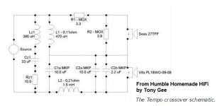
FWIW, single coil tweeter circuits can be much less simplistic and more efficient. Tony Gee at Humble Homemade Hifi uses them a lot.
Humble Homemade Hifi
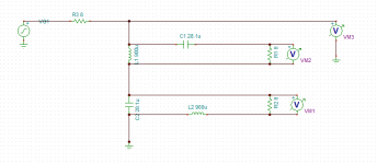
As in this unchambered familiar SEAS 27TFF example with 2400Hz crossover below:
But not dead yet. We have still to get the constant resistance circuits, the constant amplitude and the transfer functions for higher orders knocked into shape. In other words, get some real insight.
FWIW, single coil tweeter circuits can be much less simplistic and more efficient. Tony Gee at Humble Homemade Hifi uses them a lot.
Humble Homemade Hifi
As in this unchambered familiar SEAS 27TFF example with 2400Hz crossover below:
Attachments
Thanks Dave, I think
John.
If it helps I can see your concerns, but it gets complicated after that. I believe you are a highly qualified and exceedingly good mathematician. I wouldn't presume to challenge you there. However a word on my own behalf, I wrote for myself complete crossover simulation software which I began over 20 years ago. My point is simply this, if you were to claim that you were pioneering circuits before I was discovering them, I didn't know about it at the time.
I did look at your pages earlier, and if I didn't give them their dues, I'm sorry. My interests fluctuate and perhaps with the attitude of myself or the thread at the time I overlooked them. For what it's worth, I'm now playing with the Sonus Faber style high pass filter myself.
I may have a different view to you on the merits and methods of re-hashing. Though better used sparingly, I feel it is a part of the way a site like this works as illogical or disorganised as that may seem. I'm not looking to put you on a pedestal, but where I have been posting here I have felt secure in knowing others more experienced than myself have been watching over the thread.
Allen
Now this is something I would like to put my eyes one, I've always been curious about the way SF does it, at least almost as much as the Fritz Carbon 7 speakers that use this king of XO and claims an impedance of 8ohm.
Thanks Dave, I think
John.
If it helps I can see your concerns, but it gets complicated after that. I believe you are a highly qualified and exceedingly good mathematician. I wouldn't presume to challenge you there. However a word on my own behalf, I wrote for myself complete crossover simulation software which I began over 20 years ago. My point is simply this, if you were to claim that you were pioneering circuits before I was discovering them, I didn't know about it at the time.
I did look at your pages earlier, and if I didn't give them their dues, I'm sorry. My interests fluctuate and perhaps with the attitude of myself or the thread at the time I overlooked them. For what it's worth, I'm now playing with the Sonus Faber style high pass filter myself.
I may have a different view to you on the merits and methods of re-hashing. Though better used sparingly, I feel it is a part of the way a site like this works as illogical or disorganised as that may seem. I'm not looking to put you on a pedestal, but where I have been posting here I have felt secure in knowing others more experienced than myself have been watching over the thread.
Allen
I don't claim any credit for any of this stuff. I was just doing it back then for the sake of doing it. One of the first speakers I designed, back in the late 70's, was a 4 way using series crossover. I was doing x-o simulations on Cray main frame computer back then because, well, there weren't any PCs.
I guess I would not take credit for anything on crossovers, other than some stuff I actually did do that no one else did. But that is very limited and even that is based on things that came before.
Like I said, this all seems like a history lesson to me. Hope someone gets something out of it. I really don't understand the point of the thread. There is some commentary that this stuff isn't in the public domain. I would beg to differ, but the point is that posting will not accomplish that as this thread, as all these threads, will ultimately fade into oblivion and what good technical info it may contain will be buried in the endless bickering and meaningless commentary (including mine).
Anyway, I think I will just try to stop clicking on this thread as I don't have anything positive to contribute. That is basically because I don't see any positive advantages to series crossover. Commercial speaker companies using them, regardless of the hype they may put out, are most likely using them because they are cheap/simple to implement.
I have stated what Fried did and constantly told I am wrong. Fried used the baffle width to his advantage and did not add a secondary inductor which raises the driver Qts.
Peaking the Q of the corner frequency achieved this.
Every series crossover plan I have from the company used the mid bass woofer voice coil inductance as L1
I have been told that you do not use large value air core inductors of 12 mh to due a sub crossover. I guess using cap values of 150-300 mfd are also wrong when some use 2 voice coils in parallel.
Pie is the biggest constant denominator in every formula and I would not criticize this fact.
Fried found the correct values by doing the math and a lot of trial and error.
There are many constant denominators in many of the Fried series designs.
There are many commercial designers that test their designs outdoors.
Why not build one and just listen. I have never burnt out a driver with them. They do produce clean high spl..
The back of my house is entirely open so I frequently do listen to my speakers at 98-100db at 1 meter being in other rooms.
I would not listen at these levels in a room of less then 400 square feet.
Long term listening at 80 db does cause hearing loss.
It does require a large amp since the subs play flat to driver resonance in 1/4 W t-lines..
...........
Anyway, I think I will just try to stop clicking on this thread as I don't have anything positive to contribute. That is basically because I don't see any positive advantages to series crossover. Commercial speaker companies using them, regardless of the hype they may put out, are most likely using them because they are cheap/simple to implement.
John, I respect very much the little I know about your work and I'll never reach close enough of it (nor do I try to).
This affirmation of yours makes me wonder, apart from all new digital dsp stuff, keeping on analogical XOs, why I never get so 'musical' parallel crossovers as I do with series ones. I keep trying, I get better curves and measures, but never the same sound. Don't get me wrong, I tried the series ones for mere curiosity, and I always keep coming back to them now.
AllenB, are you getting the pattern on the third order networks yet?
1st and 2nd order constant resistance and constant amplitude networks seem to be done and dusted. Just Butterworth and Linkwitz-Riley at heart. Though I'm not entirely sure what a Solen Split first order does...
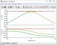
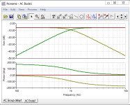
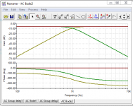
But I'm getting bogged down on 3rd order. Can't get the impedance (the brown line) flat at the moment, though I think this is very close to the constant amplitude filter. Using Tina here:
1st and 2nd order constant resistance and constant amplitude networks seem to be done and dusted. Just Butterworth and Linkwitz-Riley at heart. Though I'm not entirely sure what a Solen Split first order does...
But I'm getting bogged down on 3rd order. Can't get the impedance (the brown line) flat at the moment, though I think this is very close to the constant amplitude filter. Using Tina here:
Attachments
Last edited:
Speaker dave if you use 8ohm drivers you go for 8ohm by the use of resistors in Zobel and tweeter R2 . The simulations being done show using a resistor changes everything. Use a 15 ohm resistor in parallel of tweeter in 8ohm designs. A 10 ohm resistor in 4 ohm designs.
These designs are based on impedance.
Led meters a friend of mine has showed me how many watts I am driving the speakers with.
These designs are based on impedance.
Led meters a friend of mine has showed me how many watts I am driving the speakers with.
@John, I appreciate that a thread is no fun if you don't have a current interest in it. Still, it may change. (I wish I had had the chance to use a Cray )
@jgv, So far I am crossing only a tweeter using two resistors and an inductor. If anything I'm getting the impression of a more smooth response due to reduced impedance interaction. The system impedance is more smooth as well, but as David has pointed out there may be low spots.
@System7, how about we settle on the topology? Will the final shunt pair remain independent or joined?
)@jgv, So far I am crossing only a tweeter using two resistors and an inductor. If anything I'm getting the impression of a more smooth response due to reduced impedance interaction. The system impedance is more smooth as well, but as David has pointed out there may be low spots.
@System7, how about we settle on the topology? Will the final shunt pair remain independent or joined?
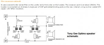
I'm not sure it makes much difference actually, except to wiring the driver polarity. But tweeter and bass shunted together seems to be most people's convention. As in Tony Gee's diagrams.@System7, how about we settle on the topology? Will the final shunt pair remain independent or joined?
I'm hoping there is a flat impedance third order series lurking at some set of values at 1000Hz. Just not getting it...
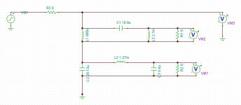
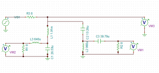
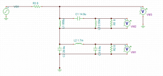
@speakerdave. I am using an 8 ohm source resistor as a convenience to easily measure the overall impedance, which is usually flat for paired butterworth filters. This is nice because such a load won't be affected by the type of amp you have. You can see the impedance is flat 8 ohms here for 2nd order butterworth series filter. Usual 12dB per octave and -3dB crosover points.
Attachments
So the 8 ohms in front is for modeling but wouldn't be used in a built up network. (also explains the 6dB drop)
Which is the impedance curve? The phase curves are of network voltage? 180 degrees apart means the tweeter polarity should be flipped? And are R1 and R2 real added resistors or are they the simulated drivers?
David
Which is the impedance curve? The phase curves are of network voltage? 180 degrees apart means the tweeter polarity should be flipped? And are R1 and R2 real added resistors or are they the simulated drivers?
David
Last edited:
VM1, VM2 and VM3 voltage sensors give the three curves. VM3 is the brown one, and measures voltage relative to earth. It would have a 3dB peak in it for a Linkwitz-Riley filter which is not constant resistance. The subsequent curves ARE affected for the L-R filter, but not the butterworth. 2nd order butterworth has a 3dB amplitude peak. I quite like modelling the 8 ohm resistor, because I have a cunning scheme to replace it with a 8 ohm LR bafflestep correction. R! and R2 are simulated drivers. I'm not too worried about that, because you can simulate a bass as a coil and a resistor, so it will be just a question of replacing an inductor with the speakers inductance. The tweeter is easily corrected with a zobel or some padding. Polarity is not an issue at this stage. Get that right later.So the 8 ohms in front is for modeling but wouldn't be used in a built up network. (also explains the 6dB drop)
Which is the impedance curve? The phase curves are of network voltage? 180 degrees apart means the tweeter polarity should be flipped? And are R1 and R2 real added resistors or are they the simulated drivers?
David
In fact the third-order parallel Butterworth is also flat impedance, and IIRC, flat amplitude. I'm just hoping AllenB can do better than me at some component values for the series 3rd order. My 0.5, 4/3 and 1.5 ratio really didn't hack it.
Attachments


Last edited:
System 7,the ratios that suit a third order constant resistance series circuit are 0.67R, 1.33R and 2R. The second order case in theory has a 3dB rise,but with real world speakers, where we measure the parameters and design the xover accordingly; the problem is non-existant.Labouring the point a little further,to achieve the 3dB gain would require the drivers to be co-incidently mounted and have identical amplitude velocity characteristics in the xover region .Peaks an dips occur by virtue of spacing and phase effects even with perfectly flat(freq response) drivers.Text book explanations are not helpful in the real world and the current fad concerning baffle step compensation is yet another example of "heading off madly in all directions."
That's helpful, VaNarn.System 7,the ratios that suit a third order constant resistance series circuit are 0.67R, 1.33R and 2R.
System7. I notice that on-axis the drivers are in quadrature, does this count?
Yup.the current fad concerning baffle step compensation is yet another example of "heading off madly in all directions."
Attachments
Though I'm not entirely sure what a Solen Split first order does...
Hi,
Neither am I and like assymetric 1st order parallel I don't think a series
version of the solen split (-6dB x/o point instead of -3dB) is possible.
It seems to me the purpose of the solen split is where your crossing
over two drivers at a point where they both begin to roll-off, the mid
above that point and the tweeter below.
If your lucky the solen split values will end up approximating 2nd order
L/R acoustic, if your unlucky the standard butterworth arrangement
might give a better acoustic result.
I can't find any information describing what the the problem
is that the Solen Split is supposed to fix and how it does it.
rgds, sreten.
BTW your filters will behave differently with a 8 ohm source impedance
and with zero source impedance, the two cases are not the same.
(TinaTi has an impedance meter function, replaces the voltage source.)
Last edited:
System7. I notice that on-axis the drivers are in quadrature, does this count?
Drivers in quadrature will force non-symmetric polars with a peak in one direction and a dip in the other. Symmetry only comes with LR or LR-like in-phase networks. I assume that Butterworth targets aren't the only option? What about unequal corner shape (high Q on one side, low Q on the other)?
In my oppinion, aiming for constant resistance input Z will be at odds with achieving flat response. As such it is a very poor design choice.
David
Flippin' excellent post, VaNarn. At last someone is talking sense!System 7,the ratios that suit a third order constant resistance series circuit are 0.67R, 1.33R and 2R. The second order case in theory has a 3dB rise,but with real world speakers, where we measure the parameters and design the xover accordingly; the problem is non-existant.Labouring the point a little further,to achieve the 3dB gain would require the drivers to be co-incidently mounted and have identical amplitude velocity characteristics in the xover region .Peaks an dips occur by virtue of spacing and phase effects even with perfectly flat(freq response) drivers.Text book explanations are not helpful in the real world and the current fad concerning baffle step compensation is yet another example of "heading off madly in all directions."
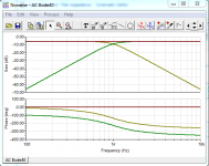
I did actually finally find a good link for the 3rd. order series crossover values @ 3kHz which were published by Jeff Bagby years back:
Passive Crossover Design Calculator
The inductor ratios were as you said 3:2:1, the capacitor ratios were a bit more subtle, eh? 3:3/2:1, and the L/C ratios and Q altogether deeper which is why my measly brain got confused...
Very nice work, AllenB.
We are there now on the constant resistance networks, which have a certain elegance. Anybody got any idea what the 4th. order series values are?
Attachments
In my oppinion, aiming for constant resistance input Z will be at odds with achieving flat response. As such it is a very poor design choice.
I assume that in a simple series network where the loads behave themselves and the drivers are of equal sensitivity, then a flat impedance curve would be indicative of a flat acoustic power response.constant resistance networks, which have a certain elegance.
It seems to come down to the usual flat power/symmetrical lobing issue, of which the second option is normally preferred, so why not allow the impedance to peak? You could always conjugate it.
You can approximate it using only damping. The effective slope near the crossover will be less than first order, but otherwise the benefits are the same.I don't think a series version of the solen split (-6dB x/o point instead of -3dB) is possible.
The problem it is supposed to reduce is the assymetrical lobing, whilst retaining a flat on-axis response. This means there should be no phase difference between the drivers on-axis, and they should be 6dB down at the crossover point.I can't find any information describing what the the problem
is that the Solen Split is supposed to fix and how it does it.
By pulling the crossover points apart, the 6dB points can be matched easily enough. The phase, which is already 90 degrees separated will separate further. Reversing one of the drivers will bring them closer than before.
However the phase responses will still not meet up and so there will still be some lobing. The drivers will not sum entirely on-axis and there will be a droop of a couple of dB. The full response will come in above or below. I have typically been of the notion that a 4.5dB compromise split makes sense.
- Status
- This old topic is closed. If you want to reopen this topic, contact a moderator using the "Report Post" button.
- Home
- Loudspeakers
- Multi-Way
- Sreten & Speakerman go at series XOs