How much resistance (DCR) is your crossover designed to tolerate?
Have you measured the DCR of your existing inductor?
I don't know how can I find these parameters

Theory says that if the resistance of the inductor is less than 10% of that of the speaker, then it may be considered insignificant. This means 800mΩ or less when an 8Ω speaker is used. There is nothing exact about this. Higher resistance could be used but it is sensible to try to keep the coil resistance (or better, the sum of all resistances in series with the woofer) below 0.8Ω.
The resistance will make a small difference to the crossover which can be adjusted for, and then it won't be a problem. Some of this adjustment can be done by changing the tweeter level (resistor) if necessary. In cases where high power is needed, the coil resistance can make it become hot, so a larger coil may be used.
The resistance will make a small difference to the crossover which can be adjusted for, and then it won't be a problem. Some of this adjustment can be done by changing the tweeter level (resistor) if necessary. In cases where high power is needed, the coil resistance can make it become hot, so a larger coil may be used.
I didn't understand how can I choose the value of the parallel resistor 10ohm etc.The new impedance
We'll need to know what the impedance is now, in order to work out the values to use later in the crossover. Estimating the 'typical' impedance value near the crossover frequency will be good enough for our purposes, and is not too difficult.
This example tweeter is a 6 ohm tweeter. Looking at the white curve on the plot below (which is the published curve from the spec sheet), the impedance goes to around 6 ohms at 2kHz, where our crossover will be. This impedance 'dip' region is not uncommon for the chosen crossover point because it happens above the resonance where we often choose to cross. For an 8 ohm tweeter we might assume it will be 8 ohms at this point (it isn't really that critical as long as we don't do anything unusual or assume too much).
Because the two blue plots in the image below will not be given on the spec sheets, we need to figure in the effect of the resistance we put in parallel with the tweeter, and this is how to do it. Start with the rated impedance of the tweeter (such as 8 ohms but in this example it is 6 ohms). Multiply this by the resistor you put in parallel, then divide this by the amount you get when you add the two. For example, a 6 ohm tweeter and a 10 ohm parallel resistor…. (6 x 10)/(6 + 10). This equals 3.75 ohms. Write your value down.
There is not one perfect value, simply the smaller the resistance the better the effect. However too low can be a problem for the amp. This is a compromise solution intended to give good results for the effort.
A better way to deal with an impedance peak is to use a tuned circuit, which involves a resistor, inductor and capacitor in series with each other. This is used in place of the resistor. These values could be calculated though you might get the best results using a circuit (crossover) simulator.
A better way to deal with an impedance peak is to use a tuned circuit, which involves a resistor, inductor and capacitor in series with each other. This is used in place of the resistor. These values could be calculated though you might get the best results using a circuit (crossover) simulator.
I've been asked about constructing a crossover. There are a few things that an experienced builder might do...
Joints could be made with clips (as I do when testing) or the leads twisted, but this will become unreliable with time. Twisting then soldering is preferred. Screw terminals are another good option. When soldering, wires should be laid overlapped end to end rather than side by side and then twisted snugly. Soldering is best with practice and should be done quickly to avoid damage to the components (spade connectors might be used with tweeters for this reason).
Securing the components to something prevents the leads from breaking over time, and can save the crossover and driver in the case of tripping over the cable. Cable ties and terminal strips are handy, and they can be easily removed or reconfigured.
Resistors need air space so they can dissipate heat. Not all crossover resistors get hot but they should be mounted off any base board and spaced from each other and from capacitors (capacitors are often plastic and not made to handle much heat). If housed inside a speaker enclosure, air flow and dissipation will be reduced.
Inductors should be mounted with consideration to other magnetic components (steel, magnets, other inductors) as their interaction can give unexpected results.
Crossover wiring should be flexible, and be able to take solder readily if going that way. For the most part it isn't critical what you use.
Last edited:
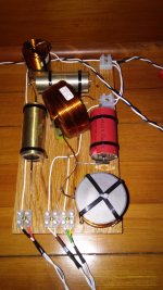
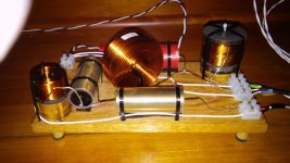
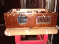
I really appreciate the knowledge you share. Regarding heat in crossovers, I've built two pair of outboard xovers. One design has no sides or top cover. The other design has sides, but no top cover, with large openings, where heatsinks are located and round openings near caps, to allow easy air flow. The resistors are mounted on the heatsinks. While both are probably overkill I thought keeping all the components at a fairly common cool temperature would be a benefit. The first Two pics are for B&W P6s. I cut blocks of wood to put the centers of all the coils on a common axis. The other two pics are for Sound Dynamics 300Ti and its coils are also on a common axis.
Attachments
Hello,
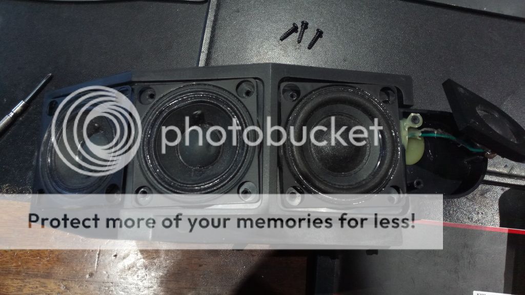
I salvaged some driver from an old Philips home theater system :

7829 (75w 8 ohms)
3531 (75w 8 ohms)
3831 (75w 8 ohms)
5829 (80w 4 ohms) Tweeter
Subwoffer, unknown as I can open the case without destroying it....
I plan to transform the Bass reflex case in a "BoomBox"... using a low cost D amp
Hot 1x TPA3116 2.1 50WX2+100W+ Bluetooth Class D power amplifier Completed board | eBay
I'll remove all defective electronic board present in the bottom of the bass reflex case and use it to host the other drivers and new amp board.
I found the service manual with some interesting informations :
If I'm correct :
Bass Reflex System: subwoofer 50-200Hz, classical, no filter needed, the amp will do
Center : 7829 (75w 8 ohms) : 160 Hz - 20 kHz, donc Full range, no filter needed, the amp will do
Surround : 3531 (75w 8 ohms) + 3831 (75w 8 ohms) : 250 Hz - 20 kHz, , donc Full range, no filter needed, the amp will do
Tweeter : 5829 (80w 4 ohms) no info... I don't know what to do... How do I know if it's a piezo (resitance based crossover) or a classic one (capacitor based crossover)
I salvaged some driver from an old Philips home theater system :
7829 (75w 8 ohms)
3531 (75w 8 ohms)
3831 (75w 8 ohms)
5829 (80w 4 ohms) Tweeter
Subwoffer, unknown as I can open the case without destroying it....
I plan to transform the Bass reflex case in a "BoomBox"... using a low cost D amp
Hot 1x TPA3116 2.1 50WX2+100W+ Bluetooth Class D power amplifier Completed board | eBay
I'll remove all defective electronic board present in the bottom of the bass reflex case and use it to host the other drivers and new amp board.
I found the service manual with some interesting informations :
Power (Subwoofer)
...
System: Bass Reflex System
Impedance: 4 ohm
Speaker drivers:165 mm(6 1/2”) woofer
Frequency response: 50 Hz - 200 Hz
...
Main Unit
...
Center speaker:
Speaker impedance : 8 ohm
Speaker drivers: 2 x 63.5mm woofer + 19mm tweeter
Frequency response: 160 Hz - 20 kHz
Left/Right surround speakers:
Speaker impedance:8 ohm
Speaker drivers: 2 x 63.5mm full range
Frequency response: 250 Hz - 20 kHz
If I'm correct :
Bass Reflex System: subwoofer 50-200Hz, classical, no filter needed, the amp will do
Center : 7829 (75w 8 ohms) : 160 Hz - 20 kHz, donc Full range, no filter needed, the amp will do
Surround : 3531 (75w 8 ohms) + 3831 (75w 8 ohms) : 250 Hz - 20 kHz, , donc Full range, no filter needed, the amp will do
Tweeter : 5829 (80w 4 ohms) no info
... I don't know what to do... How do I know if it's a piezo (resitance based crossover) or a classic one (capacitor based crossover)Hello,
I salvaged some driver from an old Philips home theater system :
7829 (75w 8 ohms)
3531 (75w 8 ohms)
3831 (75w 8 ohms)
5829 (80w 4 ohms) Tweeter
Subwoffer, unknown as I can open the case without destroying it....
I plan to transform the Bass reflex case in a "BoomBox"... using a low cost D amp
Hot 1x TPA3116 2.1 50WX2+100W+ Bluetooth Class D power amplifier Completed board | eBay
I'll remove all defective electronic board present in the bottom of the bass reflex case and use it to host the other drivers and new amp board.
I found the service manual with some interesting informations :
If I'm correct :
Bass Reflex System: subwoofer 50-200Hz, classical, no filter needed, the amp will do
Center : 7829 (75w 8 ohms) : 160 Hz - 20 kHz, donc Full range, no filter needed, the amp will do
Surround : 3531 (75w 8 ohms) + 3831 (75w 8 ohms) : 250 Hz - 20 kHz, , donc Full range, no filter needed, the amp will do
Tweeter : 5829 (80w 4 ohms) no info... I don't know what to do... How do I know if it's a piezo (resitance based crossover) or a classic one (capacitor based crossover)
I salvaged some driver from an old Philips home theater system :
7829 (75w 8 ohms)
3531 (75w 8 ohms)
3831 (75w 8 ohms)
5829 (80w 4 ohms) Tweeter
Subwoffer, unknown as I can open the case without destroying it....
I plan to transform the Bass reflex case in a "BoomBox"... using a low cost D amp
Hot 1x TPA3116 2.1 50WX2+100W+ Bluetooth Class D power amplifier Completed board | eBay
I'll remove all defective electronic board present in the bottom of the bass reflex case and use it to host the other drivers and new amp board.
I found the service manual with some interesting informations :
Power (Subwoofer)
...
System: Bass Reflex System
Impedance: 4 ohm
Speaker drivers:165 mm(6 1/2”) woofer
Frequency response: 50 Hz - 200 Hz
...
Main Unit
...
Center speaker:
Speaker impedance : 8 ohm
Speaker drivers: 2 x 63.5mm woofer + 19mm tweeter
Frequency response: 160 Hz - 20 kHz
Left/Right surround speakers:
Speaker impedance:8 ohm
Speaker drivers: 2 x 63.5mm full range
Frequency response: 250 Hz - 20 kHz
If I'm correct :
Bass Reflex System: subwoofer 50-200Hz, classical, no filter needed, the amp will do
Center : 7829 (75w 8 ohms) : 160 Hz - 20 kHz, donc Full range, no filter needed, the amp will do
Surround : 3531 (75w 8 ohms) + 3831 (75w 8 ohms) : 250 Hz - 20 kHz, , donc Full range, no filter needed, the amp will do
Tweeter : 5829 (80w 4 ohms) no info
... I don't know what to do... How do I know if it's a piezo (resitance based crossover) or a classic one (capacitor based crossover)Hi yakelkun.
Maybe the woofer doesn't produce higher frequencies due to having a bandpass enclosure. These trade bandwidth for efficiency. When designers stretch their capabilities they can get a lot of sound from a small enclosure. The low pass filter is already there in mechanical form.
The higher frequency units probably manage their low frequencies with a capacitor in series. Maybe you could check that, to make sure they weren't using some other means that you might have removed when disassembling.
The tweeter is probably dynamic (not piezo) if, you put a meter across its terminals and measure a resistance (maybe around 3-6 ohms).
Thank you AllenB for your feedback.
I checked for any capacitor or resistor on the tweeter but nothing on it. I guess the audio processor on the defective control board was doing the job.
The salvaged unit without any resistor nor capacitor inside...
The tweeter :
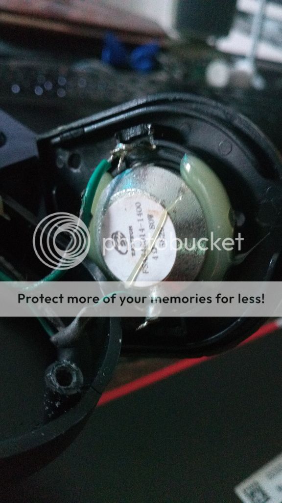
Looks non-piezo but I'm a total noob.
The assembly looks so crappy with glue everywhere...
The resistance of the tweeter is : 3 ohm (you are a mentalist)
I checked for any capacitor or resistor on the tweeter but nothing on it. I guess the audio processor on the defective control board was doing the job.
The salvaged unit without any resistor nor capacitor inside...
The tweeter :
Looks non-piezo but I'm a total noob.
The assembly looks so crappy with glue everywhere...
The resistance of the tweeter is : 3 ohm (you are a mentalist)
The higher frequency assembly looks three way, notice the wider surround on one of the midrange units. It is hard to tell whether they all had a processor (active crossover with separate amps) cutting their frequency bands. Maybe you could tell if they were all connected together to one amp. If you run these without a capacitor at least, they may not handle much power. It would be worth trying this carefully to assess their distortion. It may be worth cutting them at 200Hz.
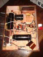
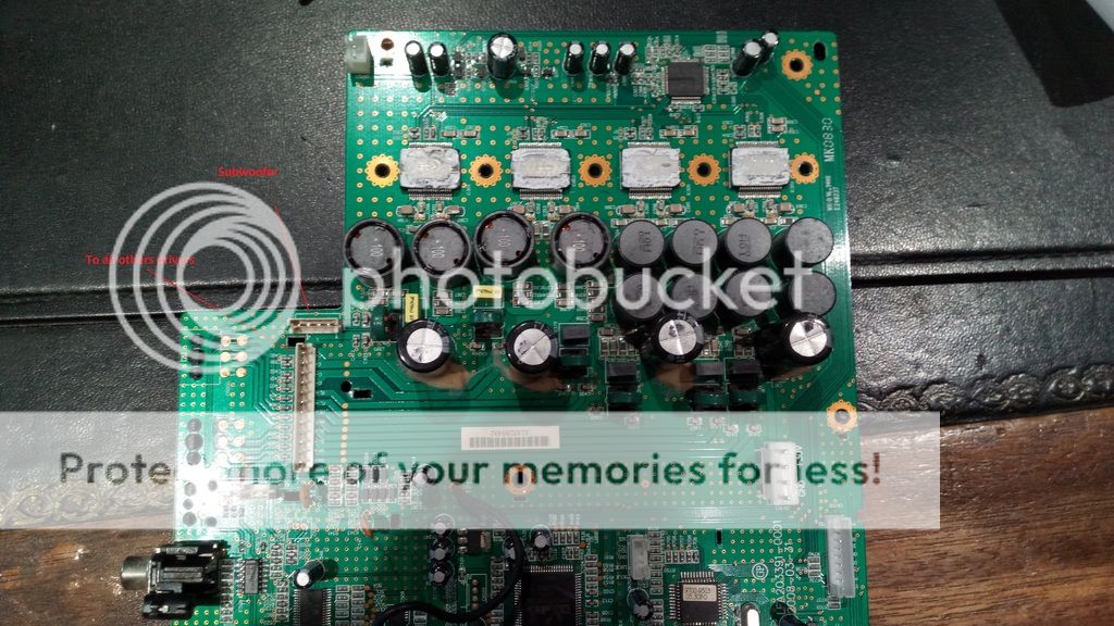
Here is the amp board with removed heatsink.
And a link to the service manual (no registering required, just some patience for the link to come just under the preview pic..https://elektrotanya.com/philips_hts6100.pdf/download.html
So, I need a crossover at 250Hz and another at 160Hz to fully use the midrange and surround speaker, if I understand your point, otherwise I'll loose lots of power as the central and surround drivers will be used out of their range (I'm really a noob, and sorry for my english).
I do my GOIYBF and found this crossover calculator :
1st Order 3 Way X-over Calculator - KBpps.com
I used :
Enter desired low crossover frequency ( FqL ) : 200 Hz
Enter desired high crossover frequency ( FqH ) : 5000 Hz (really don't have a clue.. 5k,8k,10k)
Enter impedance ( R t ) of tweeter : 3 ohms
Enter impedance ( R m ) of mid driver : 5 ohms
Enter impedance ( R w ) of woofer : 3 ohms
Results :
FqL = 202.547873 Hz
FqH = 7899.367063 Hz
C 1 = 6.631458 uF
C 2 = 157.152971 uF
L 1 = 0.100739 mH
L 2 = 2.387325 mH
I'm surprised by the results for the tweeter I red it was in a 1.5~3uF range..
But I got x1 center x2 surround and x1 tweeter + subwoofer. That's x5 speakers not 3 as in the website.. I guess Rm is to be changed, but wil I get the x2 surround in serie or parallel ? (Rm=Rsurround1+Rsurround2, or Rm=1/(1/Rsurround1+1/Rsurround2) if I remember my electricity lessons)
But it seems a little overkill to me, and moreover not adapted to my 'design' isn't it ?
I can't tell much from your amp board but there seem to be four amps. This would suggest that a passive crossover was used.
Remember there are four ways here. The woofer (the sub) is already crossed. It's not clear whether all the rest are needed or at what frequencies they are best used, this will take some experimenting on your part. The small woofers that are part of the satellites would be best crossed around 200Hz at their lower end. The tweeters don't look like they would want to be crossed lower than 5,000Hz.
If you run the small speakers without cutting the bass, you will cause over-excursion at low levels. You simply won't be able to have them loud due to the distortion. This could also damage them.
If you measure 3 ohms with your meter this would be a 4 ohm driver. Of course the impedance varies with frequency and your calculators will not be terribly accurate. Flattening the impedance may bring it a little closer to the intended effect.
Last edited:
Thanks again for your help.
I recheck the resistance of my drivers with a digital multimeter wich gave me same result than the service manual.
As I formemost need to protect the driver can I use these simple filter, can I use :
C=1/(2xPixRxFc)
R= resistance of the driver
Fc = cut Frequency
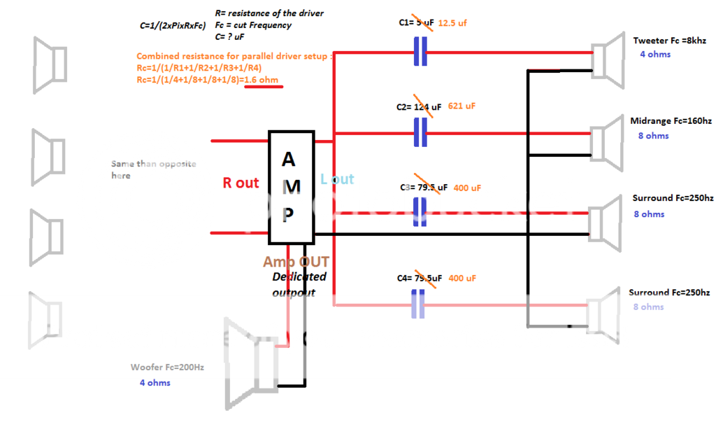
(I really sux at drawing)
But as my setup is to plug the driver in parallel, the resistance is deeply modified !!
Rc=1/(1/R1+1/R2+1/R3+1/R4)
So orange value are the good ones, am I right ?
ps: I found some cheap electronics bits..
Capacitors
I recheck the resistance of my drivers with a digital multimeter wich gave me same result than the service manual.
As I formemost need to protect the driver can I use these simple filter, can I use :
C=1/(2xPixRxFc)
R= resistance of the driver
Fc = cut Frequency
(I really sux at drawing
)But as my setup is to plug the driver in parallel, the resistance is deeply modified !!
Rc=1/(1/R1+1/R2+1/R3+1/R4)
So orange value are the good ones, am I right ?
ps: I found some cheap electronics bits..
Capacitors
- Home
- Loudspeakers
- Multi-Way
- Introduction to designing crossovers without measurement