Great info here. As I gather info for my first crossover project, I keep coming back to this thread because it's understandable.
I've seen the mid range I want to use crossed over at its resonant frequency of 800Hz in two different project speakers. I would think that is not a good idea and it should be crossed over higher, at least an octave or two above resonance. (3-way so that's the low end.)
Am I missing something here? This is the driver: HiVi DMN-A Dome Midrange-HiVi
You have shown four drivers and each has their own capacitor. If you look to the left of these capacitors there is an amp driving them all together. When the amp has a near zero source impedance (most amps do, not all but it is fair to assume a typical amp will be), it acts as a voltage source and isolates the sections.But as my setup is to plug the driver in parallel, the resistance is deeply modified !!
Rc=1/(1/R1+1/R2+1/R3+1/R4)
With a capacitor connected to the amp, only the driver combination after the capacitor applies to it. In other words you don't need to put all the drivers in the system in parallel for the calculations.
When you use two drivers in parallel (ie two identical drivers after a single capacitor) the impedance halves. Two in series doubles. Three in parallel is one third, etc.
On another (unrelated) point of view, the amp doesn't see them in parallel either because each way only applies to a certain frequency band, and the capacitor makes that 'branch' of the parallel crossover appear as a high impedance at other frequencies.
The resonance of my tweeters is 1200Hz and I cross them at 700Hz. Mine are a special case and not all drivers can or should be used that way..crossed over at its resonant frequency of 800Hz in two different project speakers. I would think that is not a good idea and it should be crossed over higher, at least an octave or two above resonance
But my point is that they could be. To make this work they first must be able to handle the excursion and the power. The impedance peak also needs to be adapted, either by flattening that peak or developing a passive filter around it or an active filter could be used. The response also needs to be adapted.
Yak,
you have shown the correct formula for a single pole filter.
But all your capacitor values do not match the frequencies and impedances you show for the drivers !
The treble driver needs a high pass filter.
The low bass driver needs a low pass filter. That might be inside the special amplifier.
The midrange needs two filters, a high pass AND a low pass.
The two Surround drivers need two filters, a high pass AND a low pass.
What you have shown will not work. It will probably blow up your amplifier.
Last edited:
I was only reading about James Watt recently. Interesting to read now about the tower.
Guys, this gentleman has assumed all the drivers in the system will be in parallel. Once the capacities are sorted all should be well.
The midrange units would benefit from low pass filters, the woofer box may be bandpass, and the filter would be optional.
yakelkun, does the woofer box have a port but no cone on the outside of the box?
I agree with you for the Amp meltdown !!
As it's a cheap board, I'd better go for 8 ohms as I red the Amp will less suffer.
I'm ready to downsize/compromise as it's a gift for my sun and foremost a way for me to learn. For example I noticed that the tweeter might not be mandatory, nor both x2 surround as frequencey range is very similar.
Thanks Andrew, I'm totally noob here, feel free to propose a schema and associated driver to drive these drivers correctly, your inputs are very welcome.
ps: thanks for Genleman")
As it's a cheap board, I'd better go for 8 ohms as I red the Amp will less suffer.
I'm ready to downsize/compromise as it's a gift for my sun and foremost a way for me to learn. For example I noticed that the tweeter might not be mandatory, nor both x2 surround as frequencey range is very similar.
AndrewT
Yak,
you have shown the correct formula for a single pole filter.
But all your capacitor values do not match the frequencies and impedances you show for the drivers !
The treble driver needs a high pass filter.
The low bass driver needs a low pass filter. That might be inside the special amplifier.
The midrange needs two filters, a high pass AND a low pass.
The two Surround drivers need two filters, a high pass AND a low pass.
What you have shown will not work. It will probably blow up your amplifier.
Thanks Andrew, I'm totally noob here, feel free to propose a schema and associated driver to drive these drivers correctly, your inputs are very welcome.
The cone is hided behind some audio mesh but I can feel it, and it's cable comes thru the wood. Note that's a 4 thin wires cable, but on the control board they are connected 2 by 2. I mean the 2 left pisn on the board are oldered together and the two right also.AllenB
I was only reading about James Watt recently. Interesting to read now about the tower.
Guys, this gentleman has assumed all the drivers in the system will be in parallel. Once the capacities are sorted all should be well.
The midrange units would benefit from low pass filters, the woofer box may be bandpass, and the filter would be optional.
yakelkun, does the woofer box have a port but no cone on the outside of the box?
Today 08:54 AM
ps: thanks for Genleman
It sounds like I was wrong about that then. You may have a normal closed or vented woofer. There are three ways that the high frequencies might be dealt with. Maybe the woofer gets the high frequencies but can't produce them well. This is the cheaper option and would benefit from you adding a good filter. Maybe the woofer already has an inductor (coil) doing this and that's ok.The cone is hided behind some audio mesh but I can feel it, and it's cable comes thru the wood. Note that's a 4 thin wires cable, but on the control board they are connected 2 by 2. I mean the 2 left pisn on the board are oldered together and the two right also.
I have seen a system that had amps in the woofer box, RCA plugs leading in, frequencies split by the electronics therein, wires leading out for the satellites. I think you're going to need to do some investigating. Is there power going to the woofer box? What are the inputs and outputs?
When you design a multi-way speaker to be 8 ohms, you usually use all 8 ohm drivers. It doesn't matter how many ways there are because when you split them fairly the system appears 8 ohms across all frequencies (not precisely, but that's another story).
I have seen a system that had amps in the woofer box, RCA plugs leading in, frequencies split by the electronics therein, wires leading out for the satellites. I think you're going to need to do some investigating. Is there power going to the woofer box? What are the inputs and outputs?
Only the x4 wire cable is visible:
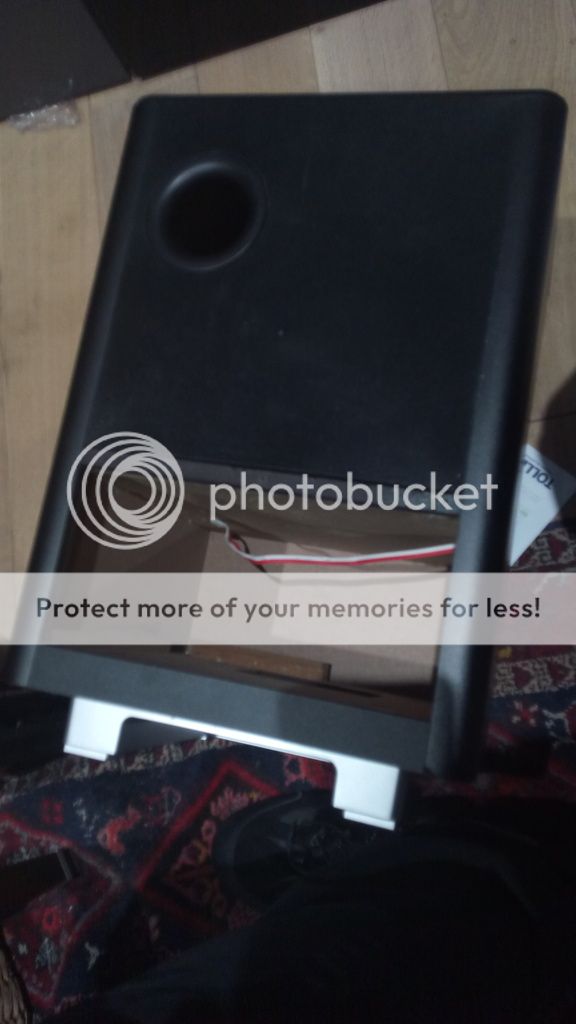
Resistance is 3.9 ohms.
The service Manual infos :
Power (Subwoofer)
Power supply: 220-240 V ~50 Hz
Power consumption: 150 W
Standby power consumption : Normal standby : <3 W
Low standby : < 0.3 W
System: Bass Reflex System
Impedance: 4 ohm
Speaker drivers:165 mm(6 1/2”) woofer
Frequency response: 50 Hz - 200 Hz
Dimensions (WxHxD): 295 x 440 x 295 (mm)
Weight : 10 kg
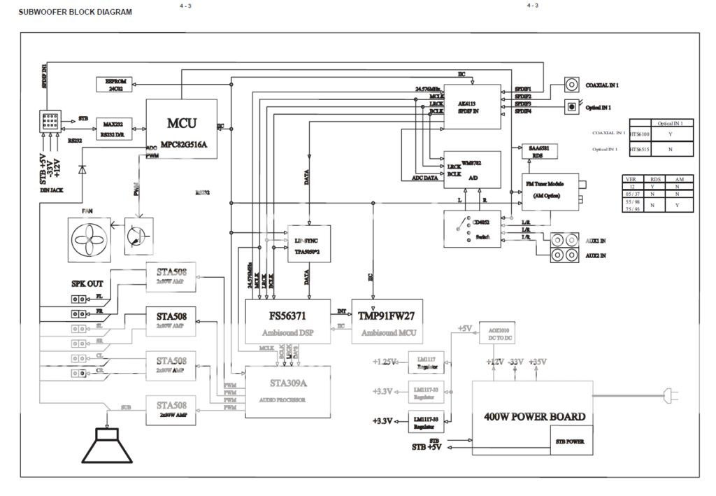
P.21 the diagram board.
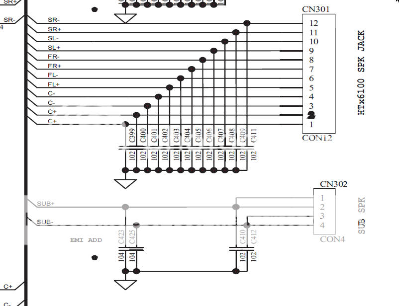
P.59 it look like filter to me..
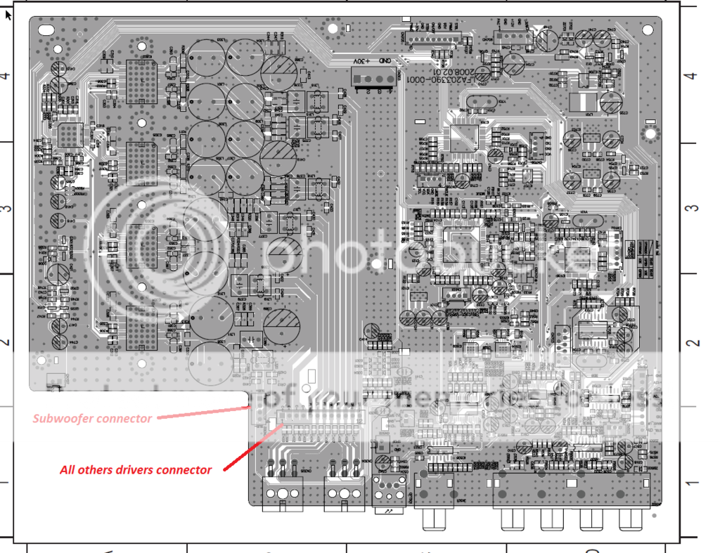
P.60The board

I'm not sure those capacitors are important at audio.P.59 it look like filter to me..
Your amps drive front/centre/surround, left/right. They would not seem to drive low/mid/high separately meaning they aren't involved in dividing the bands for the speaker drivers. Maybe the drivers can handle being run full range. Maybe there are passive crossover components on the board. Maybe you should treat them all as separate drivers and start your own design with them...
I think you are right.
I plan to simplify the design using the surround the center and bass to start.
So I'll need this kind of filter :
right ?
If right I still lack the cut frequecy resistance value, as I learn the value vary a lot depending of frequency. I red about ARTA but I'm not sure of my skill and don't want to risk my PC soundcard
I found some french video who explained to noobs like me lots of things.
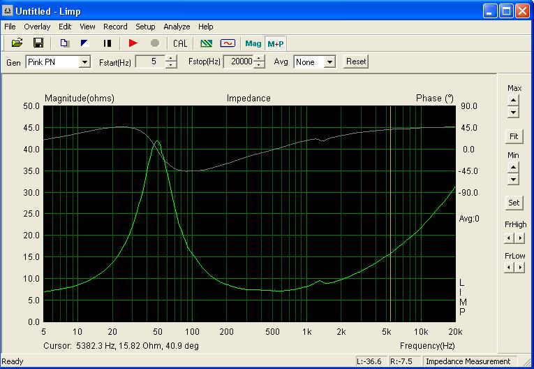
Though I discovered impedance of the driver varies a lot depending of the frequency.. So it's vital to get the HP impedance at cut frequency to calcul the filters..
Now I'm looking to use ARTA, to get the impedance curve (Hz/ohm) of each driver, as for now I now very very little of them: (source: at 17min40sec https://jipihorn.wordpress.com/2014/04/14/tutoriel-son-enceinte-acoustique-facile-partie-1/)
The curve :
Then I should decide how many driver I'll use in my DIY boombox.
To start a project like this using only Subwoofer and x2 Large range might be the real solution... I'll see depending on ARTA results.
My problem is to build the system able to get this curve, it's summed in this diagram :
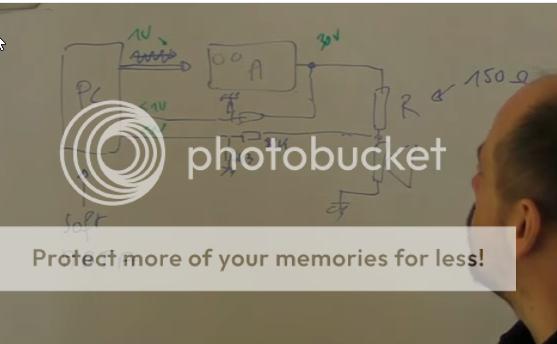
But I'm very bad at electronics.. I started a wiring scheme :
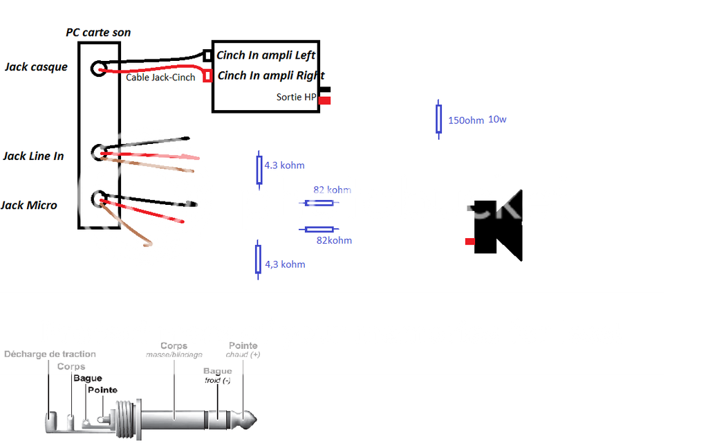
Your help would be really apreciated if you could help me to wire it correctly to avoid to burn my PC motherboard..
Sources : sorry in french but it's gold to me.
Mesure des paramètres THIELE et SMALL d'un HP : Fs, Re, Qms, Qes et Qts
https://jipihorn.wordpress.com/2014/04/14/tutoriel-son-enceinte-acoustique-facile-partie-1/
https://jipihorn.wordpress.com/2014/04/21/tutoriel-son-enceinte-acoustique-facile-partie-2/
https://jipihorn.wordpress.com/2014/05/19/tutoriel-son-enceinte-cacoustique-facile-partie-3/
https://jipihorn.wordpress.com/2014/05/09/quel-type-denceinte-choisir/
Though I discovered impedance of the driver varies a lot depending of the frequency.. So it's vital to get the HP impedance at cut frequency to calcul the filters..
Now I'm looking to use ARTA, to get the impedance curve (Hz/ohm) of each driver, as for now I now very very little of them: (source: at 17min40sec https://jipihorn.wordpress.com/2014/04/14/tutoriel-son-enceinte-acoustique-facile-partie-1/)
The curve :
Then I should decide how many driver I'll use in my DIY boombox.
To start a project like this using only Subwoofer and x2 Large range might be the real solution... I'll see depending on ARTA results.
My problem is to build the system able to get this curve, it's summed in this diagram :
But I'm very bad at electronics.. I started a wiring scheme :
Your help would be really apreciated if you could help me to wire it correctly to avoid to burn my PC motherboard..
Sources : sorry in french but it's gold to me.
Mesure des paramètres THIELE et SMALL d'un HP : Fs, Re, Qms, Qes et Qts
https://jipihorn.wordpress.com/2014/04/14/tutoriel-son-enceinte-acoustique-facile-partie-1/
https://jipihorn.wordpress.com/2014/04/21/tutoriel-son-enceinte-acoustique-facile-partie-2/
https://jipihorn.wordpress.com/2014/05/19/tutoriel-son-enceinte-cacoustique-facile-partie-3/
https://jipihorn.wordpress.com/2014/05/09/quel-type-denceinte-choisir/

- Home
- Loudspeakers
- Multi-Way
- Introduction to designing crossovers without measurement