Yes, if you understand the trade off.Does it work this way? I mean, could I just add a low pass and high pass circuit in order to make it 4 way without changing the whole circuit?
A crossover will be ideal if the circuit is correct, the drivers are identical and they are bolted into the same cutout. Although a real crossover involves different sized drivers and different driver locations, which can mean different interactions with the room, different directivities to consider, and imperfect coupling between the drivers including such effects as lobing.
A good crossover will minimise these issues and can be close to perfect.
The point is simply to consider the benefits before adding a crossover.
The radius of the roundover affects the frequencies it works above. As a rule of thumb, a 15cm radius is considered quite useful.with rounded edges.
No reason it wouldn't, if done well and the amp is OK with it.If I use all 4 ohm drivers for a 4 way design, would it be problem with the impedance?
It used to be that 4 ohms meant a car speaker, which could have a lower sensitivity with greater coil to magnet gaps to deal with the vibrations in this environment, but I wouldn't jump to that conclusion these days.
I think he meant to type 15mm roundover radius.a 15cm radius is considered quite useful.
I meant as a maximum. A radius smoothes the transition when it is 1/4 wavelength. We are most sensitive at 3k5Hz, suggesting a 2.5cm radius is minimally suitable, depending on what can be achieved on the cabinet at that point anyway, I guess.
It has also been shown that our sensitivity to diffraction reduces by 500-700Hz, hence the recommendation for the larger radius, and the implication that you may not need to go further than this.
The other audible aspect of diffraction, the frequency response issues, remain but can sometimes be dealt with by what would normally be more questionable means, once below this frequency. Otherwise an even larger radius would help.
Last edited:
What about my enclosure plan?
Approximately 35-37cm wide. 110cm overall height. I will make a larger radius from top, at the tweeter's side, and reduced little by little till it get to the woofer's side.
Just like sony ss ar1.
About mid and woofer cross frequency. Could they crossed lower? Maybe 350hz
It would be very helpful if you would give an illustration pictures to show what's going on.
The mid would be SS 12MU illuminator, and woofer SS 22W revelator.
Based on the SS spec graph, mid driver seems capable to go pretty low in an ideal box condition. But seems like my enclosure is not ideal.
So I need to know how low it could go to compensate a potential baffle step issue in my designed enclosure.
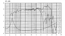
Here I attach 12MU official SS graph at the first pic. And the second picture is the 22W.
Approximately 35-37cm wide. 110cm overall height. I will make a larger radius from top, at the tweeter's side, and reduced little by little till it get to the woofer's side.
Just like sony ss ar1.
About mid and woofer cross frequency. Could they crossed lower? Maybe 350hz
It would be very helpful if you would give an illustration pictures to show what's going on.
The mid would be SS 12MU illuminator, and woofer SS 22W revelator.
Based on the SS spec graph, mid driver seems capable to go pretty low in an ideal box condition. But seems like my enclosure is not ideal.
So I need to know how low it could go to compensate a potential baffle step issue in my designed enclosure.
Here I attach 12MU official SS graph at the first pic. And the second picture is the 22W.
Attachments
What do you want to see pictures of?It would be very helpful if you would give an illustration pictures to show what's going on.
I can tell you that you can make compensation regardless of the crossover frequency you choose.
If you want to line up that compensation with a crossover to make it easier to do without measurement, a baffle simulator would be a good way to research the specifics of your baffle rolling out. Maybe don't get too caught up on the simulated higher frequency issues at this point.
I think the 12MU could cross lower than 350Hz but I have no experience with it.
What are your concerns?What about my enclosure plan?
Have you considered the floor bounce of the woofer and mid?
You're welcome roomgain. A couple of books I found helpful when I was in your shoes, one was written by Vance Dickason and one by David Weems. Other information on this site can bring you through all stages up to state of the art if you read it with the DIY mentality (and do the right searching). All the best.
Flattening Impedance with dual woofers
I'm a newbie to crossover building. I have built many speakers, focused on the cabinet and speaker selection mostly. I have been using any random crossovers I could get my hands on, and arbitrarily sticking them into the cabinet. Although a pretty horrible approach, with horrible results, I have learned allot just working with whatever I had...
I have been studying a good bit, and think I'm at a good point to try to start building my own crossovers. I have an omni mic and software, but that is a little over my head right now. So, I'm using the "Introduction to designing crossovers without measurement" thread on this website to build my first custom crossover. GREAT THREAD FOR NEWBIES!!!! I'm thinking that taking this approach for a while will help build my knowledge to a point where I could utilize my omni mic down the road.
I am building a portable stereo speaker box, with dual 3" (6ohm) woofers, and dual 2" full range speakers (tv speaker buy outs from Parts Express).
So, my first question,
When flattening the impedance for the woofers, do I use the Re & Le specs as they are, or would the be different when 2 woofers are wired together? I am assuming that probably the Re would be effected, not sure about the Le spec...
Secondly, When flattening the impedance on a woofer, does it lower the overall impedance value like it does with a tweeter? I am using a little Parts Express 50x50 watt amp board for the woofers (and a 15x15 Tripath amp for full range) which is rated to handle 4 ohms. Right now I have the woofers wired in parallel for 3 ohms, and the amp seems to push them fine. Would I be better of wiring them in series for 12 Ohms? The amp has plenty of headroom at 50 watts to push the dual woofers which are 30 watts combined. If flattening the impedance lowers overall impedance, then I know I certainly need to wire the woofers to 12 Ohms, as I would not dare want to run the amp on a load any lower than 3 ohms.
Thanks for any feedback!!!
B
3" full range with a power rating of 15W sounds wrong.
I suspect that 3" full range is more like 5W to 7.5W (half the peak 15W rating).
If that is 7.5W into 6ohms, then a 50W into 8ohms amplifier is too strong.
The 50 becomes ~35W into 12ohms. Your two 3" speakers in series becomes 15W into 12ohms. That's a much closer match amp to load. Upto double the speaker power for the amplifier is quite good to help avoid clipping and the distortion that ensues.
The 3" speaker will not like low bass. Consider a steep (4 pole or steep) high pass filter before the amplifier to limit damage to the little 3" drivers.
Two of the same woofer in parallel will give half the impedance, this is the situation across the plot which varies with frequency. You need to halve the values for resistors you'd choose for a single driver, and double the capacitances.
When you work on the impedance you would normally aim to reduce only the regions that are higher than they otherwise would be.
When you work on the impedance you would normally aim to reduce only the regions that are higher than they otherwise would be.
Second question: I am using a 4 inch bass driver @ 8 ohms. Audax AM100Z0. I have chosen to use a second order 12db/8ve for the tweeter @ 2500hz per manufacturer's spec (Linkwitz). I have chosen a 2mh coil @6db/8ve for the bass driver. Therefore the x-over is at 625hz (Butterworth), resulting in 2500 down 12db@ 2500hz. (625, 1250, 2500).
I have built a 4.75 liter box for this set-up. Seems ok so far.
Any yeas or nays?
I have built a 4.75 liter box for this set-up. Seems ok so far.
Any yeas or nays?
This is a common point of confusion with series circuits. In this case I'm referring only to the two components which are in series, but it applies elsewhere as well.For the Zoebel network, I've noticed that -in the drawings- the resistor is placed on the positive side and the cap on the negative. I've always run this the other way around. I assume I have done this incorrectly?
A series circuit is a bit like a train.. you can rearrange the carriages, you can pull it forward or backward and in any case it weighs the same (the impedance is the same).
You're welcome. With regards to your other question I'd suggest you need to balance the sound throughout the crossover for the best effect. This is going to come down to two things.
Firstly that the two drivers have a comparable radiation pattern throughout the region (which they often will in an ordinary speaker, except perhaps around the upper end of the woofer response) and secondly that the crossover reasonably divides that between the two. This way both drivers are doing the same thing.
What this means is that both drivers are putting the same sound into the room, and in particular in the direction of the listener.
Except of course that they are not in the same location, but this ordinarily can't be helped, and doesn't have to be an issue.
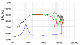
Your mid/woofer is crossing slowly at the top end by your description. More often than not, this is the region where a typical speaker has a reduced output (if there is an issue of this kind). Not that you should have much of an issue using the smaller diameter driver that you have listed. If you have any concerns this may be somewhere to look at.
Further to this it is normally best to have either a flat or slightly downward sloping response toward the top end. If the response peaks upward within the midrange and lower treble the issue will probably be obvious.
Firstly that the two drivers have a comparable radiation pattern throughout the region (which they often will in an ordinary speaker, except perhaps around the upper end of the woofer response) and secondly that the crossover reasonably divides that between the two. This way both drivers are doing the same thing.
What this means is that both drivers are putting the same sound into the room, and in particular in the direction of the listener.
Except of course that they are not in the same location, but this ordinarily can't be helped, and doesn't have to be an issue.
Your mid/woofer is crossing slowly at the top end by your description. More often than not, this is the region where a typical speaker has a reduced output (if there is an issue of this kind). Not that you should have much of an issue using the smaller diameter driver that you have listed. If you have any concerns this may be somewhere to look at.
Further to this it is normally best to have either a flat or slightly downward sloping response toward the top end. If the response peaks upward within the midrange and lower treble the issue will probably be obvious.
Last edited:
I like to err upon the side of caution. While the performance characteristics of the Audax AM100Z0 are quite good, I really hate "hot" midrange.
As an experiment (and also because the AM100Z0 is no longer built), I have elected to place the bass driver at the top, the port at the bottom in an effort to give me a pseudo MTM affect. It seems to work pretty well at this point.
As an experiment (and also because the AM100Z0 is no longer built), I have elected to place the bass driver at the top, the port at the bottom in an effort to give me a pseudo MTM affect. It seems to work pretty well at this point.
Attachments
- Home
- Loudspeakers
- Multi-Way
- Introduction to designing crossovers without measurement