Paulfx,
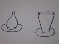
a couple things: First I'm not making mine with any internal baffle, as I'm simply planning on epoxying the baffle onto the enclosure. So I'm not sure the internal recessed baffle is necessary. However if you do end up going with it maybe consider a different shape than I am using. I drew a picture up for you. The one on the left is how I'm throwing my enclosure. I throw it "face down" this makes it easier to keep the front edge that the baffle will be glued to thick and flat. I drew a recessed baffle in there like you described. I have to say though I've made a living throwing pottery for almost ten years now, and I do trying to make that shape with the internal recessed baffle wouldn't be my idea of fun. So if you want to stick with the internal recessed baffle I would try and get your niece to throw the shape on the right for you.
Last thing, unless your niece has some production pottery experience I wouldn't give her the baffle before hand. Just simple drawing, an emphasis on making two close to the same shape, and making sure to keep the baffle extra thick.
I'll let Madisonears handle the casting questions as I've never worked with wax before. Though I will say your description seems possibly more complex than it needs to be....
Joe
edit: after rereading your post I have to say I don't exactly understand how all of this is fitting together with the added plywood.... are to planning on clamping to the internal recessed baffle with plywood on the other side? Epoxying seems pretty easy and less likely to damage the ceramic enclosure.... though maybe I misunderstood.
Attachments
Last edited:
If the epoxy sticks like crazy maybe fasteners wouldn't be needed at all. But I made a drawing myself and it's attached. This is what I understand from Madisonears - have a flat lip around the inside of the large opening so you can sandwich it between the baffle and a ring or ring segments behind it. If epoxy sticks forever, it wouldn't ever shake loose.
Attachments
Far more complicated than necessary. Epoxy poly baffle to cermaic enclosure. Done. If the surface of poly is roughened so epoxy has something to grab, it will never come loose. You better have all your internal wiring and stuffing complete, as access will be possible only through driver cut outs. The epoxy will fill small gaps, so perfect flatness of either surface is not needed.
You can drill and tap holes in the poly so you don't need through bolts to attach drivers.
Peace,
Tom E
You can drill and tap holes in the poly so you don't need through bolts to attach drivers.
Peace,
Tom E
If the epoxy sticks like crazy maybe fasteners wouldn't be needed at all. But I made a drawing myself and it's attached. This is what I understand from Madisonears - have a flat lip around the inside of the large opening so you can sandwich it between the baffle and a ring or ring segments behind it. If epoxy sticks forever, it wouldn't ever shake loose.
Sorry Paulfx,
I guess I misunderstood your previous description. Your picture should be quite a bit easier to throw than everything I was talking about.... my bad.
Joe
Hi Joe,
What radius of curvature are you envisioning for the transition from the front baffle to the side "walls?" The reason I'm asking is that it's been shown that the radius needs to be significant if your goal is to smooth the response down in the range of a few KHz. Rounding with radii of an inch or so looks neat, but it'll only affect the highest frequencies, which many of us can't hear anymore anyway.
I think you'd need a radius of at least 2-3" to make a significant difference in the audibly important few-KHz range. The wavelength of sound at 1 KHz is around 34 cm (13.5 inches). If your goal is to reduce diffraction effects from the baffle edges in the few KHz range you'll need a pretty large radius of curvature.
Few
Few,
I have to say I honestly don't know. I'm trying to make it as smooth a curve as I can it will certainly be smoother than the last effort. I have to say though that I'm starting to think more and more about your suggestion of simply pouring the baffle in from the back. I'm just not sure I can get the perfect curve on these enclosures simply throwing the form on the wheel. At least not with out a substantially thicker added baffle. It would be a little more work, but I'm now thinking that the best bet for perfect curve would be to throw the enclosure even thicker toward the base, then flip it over after it has dried a bit and trim it on the wheel to a perfect curve. For the record the perfect curve at least in my head would be similar to a tear drop shape, with a some what elongated tail. A sphereical front. I'm certainly going to go ahead and finish these with a cast poly baffle. However hopefully I can give it another go for the next firing with trimming the enclosure to a nice curve ending in a opening only slightly bigger than the driver in which a poly baffle could be poured. That's my thinking right now. Who knows though maybe I'm worrying for no reason and these will come out great.
Oh, and thanks for the info on what size round over is required to get diffraction down in the 1khz region. I had always figured the smoother/bigger the round over the better. I had just never seen any numbers put to it.
Joe
Glad the information was helpful.
You might fiddle around with the Falstad ripple tank applet if you want to visualize what happens when waves encounter walls with various shapes. You can set it up so that you can use your mouse to draw barriers for the sound to encounter. By playing with the frequency slider (which, of course, also adjusts the wavelength) you can visualize how sound with different wavelengths interacts with corners or curves that are large or small compared to that wavelength. It's easier to draw the enclosure walls first and then adjust the frequency slider than to keep redrawing different enclosures with different radius of curvature at the edges.
Click "stop waves" to keep the waves from driving you crazy. Then click "mouse = edit walls" so that you can draw soundproof walls around the sound source. I suggest starting with the sound source "inside" the enclosure you draw, and then try various enclosure shapes. If you leave an opening at the front (bottom as it's viewed in the applet) of the enclosure then you can simulate a driver radiating sound.
I'm not giving very good directions here, partly because I'm not sure if it will be of any interest. If it does seem interesting but you'd like more help, let me know.
Few
Last edited:
Getting Down in the Mud
This past weekend, my niece was talking about firing some works. I have just got to take a "crack" at this! I think I'll try my hand at aperiodic enclosure pairs for a generic 7" driver kit. 3 or 4 pairs of rectanguloids (sounds like a word), each the same shape, but with different blends of clay aiming for the lowest possible ringing. Open fronts with a lip. Little sarcophagi. I will look back at the entries here to see what clay is the deadest. I'm open to blends of paper dust, elongated brick dust particles, dried and ground horse manure - - I'll report my results.
This past weekend, my niece was talking about firing some works. I have just got to take a "crack" at this! I think I'll try my hand at aperiodic enclosure pairs for a generic 7" driver kit. 3 or 4 pairs of rectanguloids (sounds like a word), each the same shape, but with different blends of clay aiming for the lowest possible ringing. Open fronts with a lip. Little sarcophagi. I will look back at the entries here to see what clay is the deadest. I'm open to blends of paper dust, elongated brick dust particles, dried and ground horse manure - - I'll report my results.
Last edited:
- Status
- This old topic is closed. If you want to reopen this topic, contact a moderator using the "Report Post" button.
- Home
- Loudspeakers
- Multi-Way
- Ceramic speaker enclosures