GM,
Post #38,
Does paragraph 1 mean, from the centre of the driver to the edge of the baffle?
Paragraph 2, Particle density? Is this refering to air particle density or stuffing etc. Also, at which point does a box begin to show TL resonances?
Is there a specific rule of thumb here?
Bottom line; Does this mean I have accidently built some type of ferral TL without realizing it, or a tower that is leaning slightly toward TL tendancies?
Thanx again, Mick.
GM,
Bottom line; Does this mean I have accidently built some type of ferral TL without realizing it, or a tower that is leaning slightly toward TL tendancies?
Thanx again, Mick.
Not really, thogh feral is probably an accurate description
") . I suggest you read the first two pages of chapter three of your weems book again
. I suggest you read the first two pages of chapter three of your weems book again he says "As a rule of thumb make no internal dimention more than three times any other" Your hight is 6.6 X your width!!!
you built a resonant pipe (who knows what sort standing waves you have inside it... combined with the side firing and 1st order crossover, I think it was really doomed.... There are probably a couple of things you could have done that would have made it better, but the side firing would probably bring you undone anyway. Mounting the woofers 1/5th of the distance up the pipe is one of the suggested ways of taming a resonant pipe (weems mentions this a bit later in chapter three). The other would have been making it a double chamber reflext box. If you employed both those method it might have had a chance...
If it is any consolation, when I ran your box volume port dimentions (after coverting to a circular port) in unibox it looked pretty good. Certainly should have given pretty good results all things being as they should...
regards,
Tony.
Cheers Tony,
Mate, are these things feral? Too right they are!!!!!
Your double chamber idea is, or at least, could have been a good idea, I just plain didn't think down that line. Instead I just speared another bass driver in and sealed the port. That helped to a degree but they were doomed to failure from page one. I see the point on TL now, I shall certainly recite Weems chapter three again!!
Your dead right about the side firing thing, from this point on...
I plan to go wwmt in the next couple of weeks with these drivers, however I'm just not sure wheather to build seperate boxes for bass and mid/tweeter or build them as a whole unit. They may have to last a while, thats all, so they at least must be listenable.
Hey, Thanx again Tony, Thats good and uncomplicated advice, mate,
mate,
Mick.
Mate, are these things feral? Too right they are!!!!!
Your double chamber idea is, or at least, could have been a good idea, I just plain didn't think down that line. Instead I just speared another bass driver in and sealed the port. That helped to a degree but they were doomed to failure from page one. I see the point on TL now, I shall certainly recite Weems chapter three again!!
Your dead right about the side firing thing, from this point on...
I plan to go wwmt in the next couple of weeks with these drivers, however I'm just not sure wheather to build seperate boxes for bass and mid/tweeter or build them as a whole unit. They may have to last a while, thats all, so they at least must be listenable.
Hey, Thanx again Tony, Thats good and uncomplicated advice,
mate,Mick.
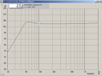
I've got a pair of these in 70" TL's and I'm disappointed with the bass; although they have extension, they are distinctly 'thin' and 'lean' sounding. My last TL's had 10" Focals and would find every loose object in the room and rattle it , so these Vifa's have been a letdown. The MJK Mathcad macro download predicted this very well; wish I had used it. What the hey, only paid $25 ea for the Vifas. Below is the predicted response for the P22 WP's. The Dayton Reference 8 sub and the Trio 8 sub are included for comparison, though at the prices it not really a fair comparison, just a reality check. The Dayton 8 classic looks very good though, and is only $29.
Low Q in a TL = expensive bass cut. Look for Q of .35 -.5.


Jim
, so these Vifa's have been a letdown. The MJK Mathcad macro download predicted this very well; wish I had used it. What the hey, only paid $25 ea for the Vifas. Below is the predicted response for the P22 WP's. The Dayton Reference 8 sub and the Trio 8 sub are included for comparison, though at the prices it not really a fair comparison, just a reality check. The Dayton 8 classic looks very good though, and is only $29.Low Q in a TL = expensive bass cut. Look for Q of .35 -.5.
Jim
Thanx Jim,
That comparison works for me! Reality is now fully in check.
Low Q inTL = Expensive bass cut, puts it all in perspective. Your attachments helped me alot here. I will purchase MJKs mathcad in the very near future, it seems to be the most respected and accurate program out there. Thank you for your most enlightening post!
I will definately go down the TL route, once I get mathcad up and running, although not with this driver, as I really do love the sound of what they can offer, if done right!
Thanx again. Mick.
I only plugged the ports with foam.......
Do you think it is probable that both speakers would have a leak that would cause the problem?
Never really liked the sound of a Two way with an 8 inch driver anyhow!
Greets!
You're welcome!
Hard to say, though if it was open cell foam I doubt you could pack it tight enough.
It depends. I mean if it's a screw hole and/or the surround isn't completely sealed and/or the frame flanges are flimsy and bend if over tightened and leak due to being under tightened for fear of cracking them in my case due to them being plastic and/or the mounting gaskets didn't seal well for some reason, etc., it could happen to both.
Me neither. When I was actively building, an 8" was for a MUZAK type system, i.e. strictly for background music or those ocean sounds, etc. mood tapes that was popular in the '70s. For other apps, 12-15" wide BW (mid) bass drivers coupled to either 5-6" 'FR' drivers or mids/HF horns ruled.
GM
Does paragraph 1 mean, from the centre of the driver to the edge of the baffle?
Paragraph 2, Particle density? Is this refering to air particle density or stuffing etc. Also, at which point does a box begin to show TL resonances?
Is there a specific rule of thumb here?
Bottom line; Does this mean I have accidently built some type of ferral TL without realizing it, or a tower that is leaning slightly toward TL tendancies?
No, from the acoustic center of one driver to another. WRT the tower design where there's a driver up high on the front and two vertically oriented drivers on the side it would be an imaginary line drawn from the center of the front driver to the center point between the two drivers on the side, then ideally this distance would be <1/4 WL of the XO point's Fh6 (upper -6 dB point). This is often an unrealistic goal, so as long as the XO point is < ~150 Hz it's acceptable to use a ~1 WL distance. This was based on the vinyl and tape sources of yesteryear, but with bass being summed mono at 120 Hz these days, this is the upper limit for me.
The air mass in the cab and separate air plug in the vent. Stuffing introduces another level of acoustic properties that can force a non homogeneous air mass into a homogeneous one (~uniform particle density), at least I think this is a technically acceptable way to describe it. Anyway, hopefully you get the 'picture'.
Well, once we move away from a homogeneous cab, eigenmodes begin forming, but until they're strong enough to impact the vent length, then they're just something to damp down since we don't want them to 'leak' out of the vent or back through the driver's diaphragm by modulating it.
I have a proprietary way I arrive at a length somewhere above the point where it starts, i.e. it has no rhyme or reason since it doesn't take the driver's parameters into consideration, so with one driver it may barely shorten the vent and another make it so short I have to increase the vent area to get it at least baffle thickness long, but MJK published a lot of math in his early works that my eyes/mind glazed over, so maybe it's buried in it. Good hunting!
Don't know, haven't researched it yet. Tower/column designs have been around for decades, but historically the vent was placed right next to the woofer/whatever because they wanted the most gain from it which meant excessive upper BW was released unabated too, so they reasoned the best trade-off was to closely couple it to the driver's front radiation rather than risk having a phantom 'mid' down low.
RCA's Harry Olson apparently didn't agree with the status quo and instead designed a MLTL in the '40s (though he called it a BR, missing a marketing chance by not patenting it) for its premier wide BW drivers that was used until it was dropped in the late '60s when sales of large speakers had dwindled to pretty much zero due to the rise of cheap high power making acoustic suspension alignments with their much less efficient drivers work well in relatively tiny cabs.
GM
Attachments
GM,
Thanks very much for for your input here, what your saying makes tonnes
of sense.
WRT, 8" 2 ways, I guess I just could not get that 'natural sound' out of them, to make the whole thing worth while, be it due to lack of knowlege, or that they are just hard for me to match with a 1" tweeter, I'm not sure. I do know that it was always less than ideal for my listening pleasure. I have heard some 'good' sounding 8" 2 ways, but to me they always seem to lack that little something that makes a speaker 'nice'. Transient response, perhapse?
The foam I used in this instance was ordinary matress foam, although I had packed it in pretty tight, I may have under estimated the forces at play here, so there could be at least some leakage there.
Thanx aplenty GM, Pleny of points for me to follow up on! Again, I apprieciate your input no end!
Mick.
Greets!
Yeah, XOing around our 2 kHz peak hearing acuity BW makes even tiny timing/phasing errors perceptible to many folks, so to be avoided like the plague IMO if not coincident and phase aligned. There's lots of debate about all this and the plethora of successful ~2 kHz two way designs adds 'fuel to the fire', but all it means to me is that some folks are more sensitive to timing errors than others, so the fact that enough folks can hear it at some level of perception enough for it to be objectionable is enough for me to err on the side of caution when designing and/or expounding on it. So, yes, it's a transient response 'thing'.
Hmm, mattress foam can be either open or closed cell, though open cell mattress foam is pretty dense, so at low signal levels may be adequate. FWIW, for smaller vents I found that old heavy duty work socks crammed in them worked well.
You're welcome! I hope you try chasing down the dip again since at present it's a real head 'scratcher'.
GM
Thanx again GM,
I will have another crack at that dip, Hopefully I will get time over the weekend . I'll be sure to keep you posted.
I must have tried a hundred different XOs for these and a couple of other 2 ways with these woofers and none hit the spot.
The three ways i'm using at the moment are crossed around 4400hz and sound much better, if not slightly 'dry' with some music, to my ear they are much more pleasing. Its the first XO I tried with them, all I had to do reverse tweeter polarity. to be honest I didn't think this would make much diference at this XO point, but it did.
Once I get rid of that dumb side firing idea, hopfully I should have something halfway decent to listen to!
I will have a good 'tweak' with these, just to see what happens, It will either make them sound better, or it won't!
Thanx again for taking an interest here, Mick.
I will have another crack at that dip, Hopefully I will get time over the weekend
. I'll be sure to keep you posted.I must have tried a hundred different XOs for these and a couple of other 2 ways with these woofers and none hit the spot.
The three ways i'm using at the moment are crossed around 4400hz and sound much better, if not slightly 'dry' with some music, to my ear they are much more pleasing. Its the first XO I tried with them, all I had to do reverse tweeter polarity. to be honest I didn't think this would make much diference at this XO point, but it did
.Once I get rid of that dumb side firing idea, hopfully I should have something halfway decent to listen to!
I will have a good 'tweak' with these, just to see what happens, It will either make them sound better, or it won't!
Thanx again for taking an interest here, Mick.
Hi Mick/GM I'm also interested in the dip, Have you looked at akabak? I downloaded it the other day after GM's comment about unibox. I've wanted something that can model a dual chamber reflex enclosure and this fits the bill. thread discussing it here ---> http://www.diyaudio.com/forums/showthread.php?s=&threadid=90362&highlight= The tutorial by Don Hills makes for a quick way to get up to speed (well at least getting something usefull out of it)... I'm very impressed with the program.. I almost tried to model Mick's feral speaker, the thing I was most interested in was the simulated polar response graphs, should really show what is happening with those side firing woofers, but then I decided I realy had enough of my own diying to worry about so put it down...
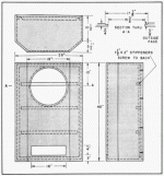
That port at the bottom of the 23L boxes really makes me wonder. I know from a theoretical point of view the dimentions are way too small to be having an effect at 80 Hz but it just looks like trouble to me... I think that if anything can possibly do an acurate model of your speakers be they the towers, or the 23L boxes, then akabak is probably the tool
Also I found that your 30L size and tuning with the port dimentions (akabak handles rectangular ports) is not quite so ideal.. I made a mistake with the conversion from rectangular to circular port, it wasn't that big but made quite a difference in the modeling... I reckon an extra 3cm on the port length would have been better.
Attached is a power plot from akabak of your 30L box with the port you have... Note I didn't work out how to model the shape of the enclosure at this point the peak is about 2db.
Tony.
That port at the bottom of the 23L boxes really makes me wonder. I know from a theoretical point of view the dimentions are way too small to be having an effect at 80 Hz but it just looks like trouble to me... I think that if anything can possibly do an acurate model of your speakers be they the towers, or the 23L boxes, then akabak is probably the tool
Also I found that your 30L size and tuning with the port dimentions (akabak handles rectangular ports) is not quite so ideal.. I made a mistake with the conversion from rectangular to circular port, it wasn't that big but made quite a difference in the modeling... I reckon an extra 3cm on the port length would have been better.
Attached is a power plot from akabak of your 30L box with the port you have... Note I didn't work out how to model the shape of the enclosure at this point
the peak is about 2db. Tony.
Attachments
The three ways i'm using at the moment are crossed around 4400hz........
Once I get rid of that dumb side firing idea, hopfully I should have something halfway decent to listen to!
You're welcome!
Note that for multi-ways a decade is considered the max acceptable BW/driver spread or 440 Hz for a 4400 Hz HF XO point with either 300-3000 Hz or 500-5000 Hz being the traditional choices.
Side firing isn't 'dumb', the late, great NHT 3.3 reference and its lower cost siblings are ample proofs-of-concept, it just needs to have a low XO point for best overall performance in a tower design.
Anyway, time constraints are forcing me to bow out of the forums for the most part, but I'll still monitor your 'adventures' in speaker design as time permits.
Good luck with it.
GM
Tony,
Thanx for all that info, You've again gone above and beyond, so to speak.
I appreciate this alot, I have downloaded akabak and will try to nut it out sometime soon. I will check your blog here, now, just to see what your up to!
GM,
Thanx alot for ALL your help, I'm a wiser man for the experience!
I wasn't refering to all side firing speakers, just these feral things! I have heard some good ones in my day as well, but it sure wasn't these ones!
I can't cross this midrange over low enough to make 'em sing, so I shall build front firing, armed with the extra knowlege and programs I now have at my disposal.
Thanx again guys Mick.
Thanx for all that info, You've again gone above and beyond, so to speak.
I appreciate this alot, I have downloaded akabak and will try to nut it out sometime soon. I will check your blog here, now, just to see what your up to!
GM,
Thanx alot for ALL your help, I'm a wiser man for the experience!
I wasn't refering to all side firing speakers, just these feral things! I have heard some good ones in my day as well, but it sure wasn't these ones!
I can't cross this midrange over low enough to make 'em sing, so I shall build front firing, armed with the extra knowlege and programs I now have at my disposal.
Thanx again guys
Mick.Hi Mick, no problem. I always think it is best to try and understand what when wrong before embarking on something new. Yeah it takes some time, but if it can be worked out, then at least the same mistake shouldn't happen again.
I just thought of something too!!! Did you ever run that sine wave on the 23L boxes outside? The big dip you are hearing may well be due to room interaction and not the speaker at all! If you get standing waves in your room then depending on where you are standing/sitting at the time of doing the measurement you might in fact be right in the null zone of a standing wave.
Do a search on standing waves and you should find some calculators, if you put your room dimentions in it might show you the problem
Tony.
Tony,
Tried everything except playing them outside, three different houses all with completly different room WxHxD ratios, all netted the same result. Also my tannoys placed in the same spot, don't exhibit the same problem, and the dip is audible from everywhere in the room. Come to think of it even the 'ferals' don't seem to have the problem. Although they have so many problems it maybe just masked well!
I will try another leak test over the weekend, I will test them outside while i'm there. I will get to the bottom of it eventually, rest assured of that!! For every action there is an equal and opposite reaction, so there MUST be a reason somewhere! I've got my money on a leak, that my lack of experience, didn't pick up on b4, I'll find it this time round, if its there!
What do you use for driver-cabnet gaskits? I use heavy duty grease (!), but I wouldn't have a clue what other people typicaly use.
Thanx again Tony. Mick.
OK looks like you have completely covered that aspect!! I don't think testing outside will make any difference at all, especially if the dip was there everywhere in the room.
I've used some stuff that Jaycar sells/sold as speaker sealer (or some such) it is like super sticky bluetack... horrid stuff really and really hard to get off once on, also makes drivers really really hard to remove!! wouldn't recommend it
The other thing I've used is draft strip from Bunnings. I've used the stuff that is about 1cm wide and maybe 3-4mm thick, I believe it is closed cell foam, it tends to compress down to almost no thickness at all, and I believe it does a good job, though I've never actually checked for leaks, as I know that my three way boxes are full of them without testing One of the reasons the next stage of my MTM project is to build new cabinets for the woofers.
Tony.
I don't think testing outside will make any difference at all, especially if the dip was there everywhere in the room. I've used some stuff that Jaycar sells/sold as speaker sealer (or some such) it is like super sticky bluetack... horrid stuff really and really hard to get off once on, also makes drivers really really hard to remove!! wouldn't recommend it
The other thing I've used is draft strip from Bunnings. I've used the stuff that is about 1cm wide and maybe 3-4mm thick, I believe it is closed cell foam, it tends to compress down to almost no thickness at all, and I believe it does a good job, though I've never actually checked for leaks, as I know that my three way boxes are full of them without testing
One of the reasons the next stage of my MTM project is to build new cabinets for the woofers.Tony.
Some kind of room response thing was one of things I first thought it was too, although I did leak test them, there was room for error in my method, so we'll see what happens there. I will put a THICK layer of grease around any problem areas, and see how they sound for a start, if the dip is still present, I will hunt for a leak, failing that I will still test them outside, just to be certain. Then failing that, well, dunno! I might try kicking and throwing stones at the buggers!!!!!!
One thing is almost certain though, if its not a leak, It must be a problem isolated to this particular design, a signature, if you will. The design before didn't have it, the design after doesn't seem to, so if I play my cards right, the next design shouldn't have it. But some other stinking problem more than likely!
Mick.
One thing is almost certain though, if its not a leak, It must be a problem isolated to this particular design, a signature, if you will. The design before didn't have it, the design after doesn't seem to, so if I play my cards right, the next design shouldn't have it
. But some other stinking problem more than likely!Mick.
SPL meter test?
Tony,
I do know a bloke who would almost certainly loan me his SPL meter, and I have a nice quite farm I can visit any time. I don't have any other equipment, but I think I may be able to run some tests and take written notes. It may help with designing a new pair if nothing else!
Anyhow just a thought.
Mick.
I recon the best test would be an impeadance plot, but an spl meter won't give you that. Only reason I say that is that if there is anything weird going on inside the cabinet, reflections, refractions etc then they should show up as anomilies in the impeadance plot.
I recon it would be interesting to put some damping material around that port and maybe even put some loose stuffing (polyester fibre or the like) in it. certainly doing some measurements with the SPL meter to see what (if any) difference this makes would be a good idea!
Tony.
I recon it would be interesting to put some damping material around that port and maybe even put some loose stuffing (polyester fibre or the like) in it. certainly doing some measurements with the SPL meter to see what (if any) difference this makes would be a good idea!
Tony.
- Status
- This old topic is closed. If you want to reopen this topic, contact a moderator using the "Report Post" button.
- Home
- Loudspeakers
- Multi-Way
- vifa p22wp-01 transmission line