Another way to look at the graph is to consider the equivalent cutoffs of each - although both are nominally 425 Hz horns, the T = 1.34 version needs to be scaled-up by about 60% to have equivalent usable cutoff frequencies. In that event, it might be even better than the AH425 - but it won't fit into an AusPost box any more.
Based on the profound differences between conicals, conicals with smoothed-radius transitions between the driver and horn (Peavey's Quadratic Throat), Dr. Geddes' Oblate Spheroid waveguide, the Tractrix, the family of LeCleac'h horns with T ratios between 0.707 and 1.34, and traditional exponential horns, it's not surprising they sound different. All of the parameters are different - acoustic impedance, the shape of directivity pattern vs frequency, internal reflections, potential mismatch between the internal flare of the compression driver and the entrance to the horn, etc. etc.
Based on the profound differences between conicals, conicals with smoothed-radius transitions between the driver and horn (Peavey's Quadratic Throat), Dr. Geddes' Oblate Spheroid waveguide, the Tractrix, the family of LeCleac'h horns with T ratios between 0.707 and 1.34, and traditional exponential horns, it's not surprising they sound different. All of the parameters are different - acoustic impedance, the shape of directivity pattern vs frequency, internal reflections, potential mismatch between the internal flare of the compression driver and the entrance to the horn, etc. etc.
Here's a power factor comparison between the 288+AH425 (thin lines) and an OS waveguide with the simulated DE250 driver (thick lines). All drivers are idealized "perfect" drivers, with the internal throat flare of the driver as part of the horn or waveguide BEM simulation. The phase plugs are NOT part of the simulation, and the drivers are assumed to be free of resonances.
The black line in the power factor is a "bulk" figure; it tells us nothing about where the power is actually going, just that it's leaving the horn and entering the room. It could leave the horn at any angle; this graph doesn't tell us where. The red lines represent the percentage of the energy reflected back into the diaphragm.
The complexity of the preceding figures - all idealized simulations with "perfect" drivers - should give an idea of the complexity of what's going on in the horn, and how FR graphs measured at one location don't tell the whole story. We haven't even looked at the time domain, CSD waterfall plots, headroom, or distortion.
Throw in diaphragm resonances and the complex behavior of phase plugs, and now you get to have real fun. Imagine a different set of CSD waterfall plots for every 7.5 to 10 degrees of emission angle and you start to get an idea of what's really happening in a physical system.
Attachments
Not done yet; here's the 288+AH425 frequency response at different distances. Again, an idealized "perfect" driver with no resonances, flat power response and no phase plug aberrations. Real drivers aren't this good, thanks to the phase plug and the limitations of physical driver materials.
Based on the data, measuring or equalizing the speaker at 1 meter or less would be a bad idea, but 2 meters or further away starts to appear more uniform and stable. You can also see why I'm contemplating a crossover topology with a series-cap highpass filter followed by a parallel notch filter to get the desired curve on the highpass function, with additional shelf-EQ to taste (this depends on listening angle, etc).
Based on the data, measuring or equalizing the speaker at 1 meter or less would be a bad idea, but 2 meters or further away starts to appear more uniform and stable. You can also see why I'm contemplating a crossover topology with a series-cap highpass filter followed by a parallel notch filter to get the desired curve on the highpass function, with additional shelf-EQ to taste (this depends on listening angle, etc).
Attachments
And just to add fuel to the horn fire, there is also the Iwata camp and the multi-cell camp! (I like both).
Certainly agree with you Lynn about the super tweeter on most horns, as they do beam. I didn't find the multi-cell to beam too much, tho maybe soemone else has found differently. Cal? GM?
The edge termination of the horn can make a big difference, for sure. Beach towels work for me.
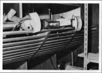
The soft or progessive edge was one of Mr. Iwata's big points. You can see it as progressive slots in the photo of his bass horns below. Oddly enough, he did not seem to use it at higher frequencies.
Certainly agree with you Lynn about the super tweeter on most horns, as they do beam. I didn't find the multi-cell to beam too much, tho maybe soemone else has found differently. Cal? GM?
The edge termination of the horn can make a big difference, for sure. Beach towels work for me.
The soft or progessive edge was one of Mr. Iwata's big points. You can see it as progressive slots in the photo of his bass horns below. Oddly enough, he did not seem to use it at higher frequencies.
Attachments
Wave Guide Zilchlab tests DE250 etc...
Good stuff here in the larger thread but you have to dig for it. Both Geddes & others have checked in to discuss and observe and see what works for both Jackgiff and Zilch & the minions....methodology of crossover / driver interactions both acoustical & electrical measurements of particular interest...
http://www.audiokarma.org/forums/showpost.php?p=2550990&postcount=4669
Thanks for the interesting posts...
If I can be abit subjective again, I've been listening to the Altec 414 in Onken enclosure and whilst it goes down low enough for me, it is sounding abit 'dry' in the bass region and I am wondering if it's due to the F3. Am waiting for a custom Shishido 801A SET before finalising the cross-overs...
If I can be abit subjective again, I've been listening to the Altec 414 in Onken enclosure and whilst it goes down low enough for me, it is sounding abit 'dry' in the bass region and I am wondering if it's due to the F3. Am waiting for a custom Shishido 801A SET before finalising the cross-overs...
jonjin said:Thanks for the interesting posts...
If I can be abit subjective again, I've been listening to the Altec 414 in Onken enclosure and whilst it goes down low enough for me, it is sounding abit 'dry' in the bass region and I am wondering if it's due to the F3. Am waiting for a custom Shishido 801A SET before finalising the cross-overs...
Not quite sure what you mean by "dry" - do you mean over damped resulting in a somewhat tight, and anemic sounding bass or something altogether different? The Onken design is sensitive to amplifier source impedance which affects the qts of the woofer significantly, it might be that your amplifier's output impedance is a bit too low for the tuning you used - try adding a small amount of resistance or use an inductor with slightly higher R. If what I have described is not the case then something else is going on. (In my case the reverse was the situation and slightly reducing the R in series with the woofer gave me the improvement I was looking for.)
panomaniac said:So Kevin you needed to lower DCR in your crossover?
This was for your 300B SET amps, right?
Hi Mike,
Yes that's right, and we're really only talking about approximately 0.25 ohms difference between the dcr of the two inductors which I would hardly have expected to be audible, but it was. I knew the original was a bit on the high side, but optimistically I expected it to be insignificant, and I finally replaced it with the considerably more expensive part I had hoped to avoid, fortunately with the expected result. Ultimately I have paid great heed to this issue as changing amplifiers does result in a marked change in the quality of the bass - one of the downsides of designing a system for an amplifier that is not a voltage source. Those SS guys have it so much simpler, most of their amps closely approach an ideal voltage source and you can count on that when you design a speaker - not so as you know with SE tube amplifiers and I designed my speakers taking this into account, even so the window is narrower than I originally expected.
kevinkr said:
Not quite sure what you mean by "dry" - do you mean over damped resulting in a somewhat tight, and anemic sounding bass or something altogether different? The Onken design is sensitive to amplifier source impedance which affects the qts of the woofer significantly, it might be that your amplifier's output impedance is a bit too low for the tuning you used - try adding a small amount of resistance or use an inductor with slightly higher R. If what I have described is not the case then something else is going on. (In my case the reverse was the situation and slightly reducing the R in series with the woofer gave me the improvement I was looking for.)
Exactly. That's why I'm waiting for the 801A SET to arrive before I finalise things... I'm still using the Behringer digital x-over. But I'll bear this in mind when choosing inductors. At the moment I'm on 12dB Butterworth at 1000Hz. The auto-align on the Behringer has also helped by delaying the mid-Onken CD. I've now repositioned it and everything is much better in focus. The whole system is hugely transparent and makes appreciating subtle changes easy.
JJ - learning loads...
jonjin said:I'm still using the Behringer digital x-over.
Modified, I hope!!
GM said:This will mimic VC heating and the effect of passive XO components, ergo the effective Qts increase that I've ~given up trying to get folks to take into account when doing a box design, but won't show the impedance tracking of a tube amp: http://www.geocities.com/dmitrynizh/LoadingTubeSE.htm
Hi GM,
What do you mean by "impedance tracking"? If you mean that the output impedance of a tube amp changes depending on the load impedance, I would be interested in hearing an explanation on what mechanism is at work. I have not seen such behavior mentioned in any reference on tube electronics. Besides, I would think that only a complicated feedback mechanism could make this possible.
Output impedance may change with drive level (a nonlinear effect) or with frequency, due to reactances in the output transformer or decoupling. Looking at tube curves, the plate resistance (and hence the output impedance) in a given operating point is given by the slope of the constant grid voltage lines, which is independent of the slope of the load line.
The web page you linked to shows how the output voltage of a tube amp changes with the load, but it has no curves on output impedance.
Returning to Hornresp, setting Rg to a non-zero value is the traditional way to model a (tube) amp with a non-zero output impedance. It was used in the days when tube amps where the only amps available, and if it was wrong to do it that way, I expect they would have discovered it.
The generator open terminal voltage will not change, but the input voltage to the driver will change in a similar way to what is shown on the page in the link.
Best regards,
Bjørn
Kolbrek said:Returning to Hornresp, setting Rg to a non-zero value is the traditional way to model a (tube) amp with a non-zero output impedance.
Harry Olson does just this in an example he provides in his book "Acoustical Engineering". In the example given the electrical impedance Rg of the vacuum tube amplifier through the output transformer is 35 ohms.
Kind regards,
David
Hello David,
My Shabda amplifer which one I use on TAD TD2001 compression drivers mouted on Le Cléac'h horns possess an output impedance of 55 ohms.
IMHO it is far better to used a current drive of the TD2001 than a voltage drive.
You can judge by yourself comparing the response curves of the TAD as measured by me at home (pulse response obtained by deconvolution of a 30seconds logsweep):
blue = voltage driven
red = current driven
http://www.diyaudio.com/forums/attachment.php?s=&postid=1531292&stamp=1212610725
about the origin of the famous hole at 1600Hz in the TD2001 compression driver see also:
http://www.diyaudio.com/forums/attachment.php?s=&postid=1532609&stamp=1212756899
Best regards from Paris, France
Jean-Michel Le Cléac'h
David McBean said:
Harry Olson does just this in an example he provides in his book "Acoustical Engineering". In the example given the electrical impedance Rg of the vacuum tube amplifier through the output transformer is 35 ohms.
Kind regards,
David
- Status
- This old topic is closed. If you want to reopen this topic, contact a moderator using the "Report Post" button.
- Home
- Loudspeakers
- Multi-Way
- Reviving the Onken