Maybe air core inductors should be correctly wound for efficiency. It is the inductance of the coil that chokes the high frequency. The better designed and tightly wound coil will form a more consistent magnetic field, therefore being more efficient, thereby doing a better filtering job.
Just my uneducated guess.
Just my uneducated guess.
Tenson said:Hi,
How can you account for the effect of series resistance on the amps control over the driver?
You may account for the frequency response, but the amp will still have slack control over the driver. I guess this would show up in a low frequency CSD plot.
Amplifier damping factor is a grossly over-rated attribute. The effect of DC resistance of the LF inductors is easily quantified, and not all that important.
MJL21193 said:Maybe air core inductors should be correctly wound for efficiency. It is the inductance of the coil that chokes the high frequency. The better designed and tightly wound coil will form a more consistent magnetic field, therefore being more efficient, thereby doing a better filtering job.
Just my uneducated guess.
But not really correct. Its the number of turns that sets the inductance and how tightly or uniformly they are wound is a minor virtually insignificant effect. Its important that the wires be glued together, but "perfect lay" is a scam.
gedlee said:
Amplifier damping factor is a grossly over-rated attribute. The effect of DC resistance of the LF inductors is easily quantified, and not all that important.
Perhaps it is easily quantified in the frequency domain but how about the time domain such as CSD? I'm genuinely asking, not arguing.
If it is not damping factor, what is your hypothesis for low DCR inductors providing seemingly better bass control? The extreme here would be actively driven bass drivers which it is generally accepted do have better control.
Off topic, I have been reading your two papers on distortion perception and the Gedlee metric
") Very interesting. Have there been any advancements on this becoming a wider accepted metric of sounds quality since they were published?
Very interesting. Have there been any advancements on this becoming a wider accepted metric of sounds quality since they were published?I have wrote that before in similar threads about components.
I can hear clearly a typical non polar from a Black Gate red non polar, or from various film caps in front of a tweeter (over 2-3k). I can hear them a lot less in front of a midrange (up to 2-3k) and I can't hear them below 1k.
A nice trick is that if it is possible, limit the high part going to the midrange with a coil, before feeding the series cap. That takes it 90% out of the picture. I don't know if its due to non exciting some resonances in the cap's structure, but it works. There is a big enough series cap in a midrange bandpass passive crossover normally, and you will be able to use a non polar there with no worries if you follow the above tip. Nice economically.
I use best film if the finances allow for tweeter. No tricks there.
Coils I use normal wire, I mount them well so not to resonate. And I use some tape or hot glue to keep em tightly wound.
I have used Alphacore foils etc but I heard no real differences. To the contrary if I was not wrong they were a little thinner sounding than magnet wire coils.
Of course I talk about same DCR and incorporated to the system's alignment and crossover.
Tenson said:
Perhaps it is easily quantified in the frequency domain but how about the time domain such as CSD? I'm genuinely asking, not arguing.
If it is not damping factor, what is your hypothesis for low DCR inductors providing seemingly better bass control? The extreme here would be actively driven bass drivers which it is generally accepted do have better control.
Off topic, I have been reading your two papers on distortion perception and the Gedlee metric
Time domain and frequency domain are just two different ways of looking at the same things. There is nothing new in either of them. The DCR does reduce the damping of the driver, but this is predicatable and no different than a small change in the Qes. A low DCR in any inductor in series with the woofer is a good thing, but it can be taken to an extreme. A good iron core inductor can have a DCR of only a few tenths of an ohm. This raised the Qes a few %, certainly a factor, but not a big one. The whole concept of Q and resonance at the LF is overrated because it is all dominated by the room acoustics anyways. In the big picture of LF sound in a small room the Qts of the woofers is a very small factor. I pay no attention to the Q of the LF of a loudspeaker system at all. I primarily care about how many woofers there are and where they are. Everything else is secondary.
The advance in distortion metrics is the realization that none of them mean much. Nonlinearity in a loudspeaker system is not very important so accurately measuring it is not very important either. It is important to look for high order distortion in the electronics, but loudspeakers can't have high order nonlinearity. I measure the Gedlee metric on my amps, but I don't measure it on my loudspeakers.
Hi,
Yes I agree that it is easy to make a good inductor. I use simple ferrite core myself. However, if one were to build a 1.5mH inductor as air-core and use 0.5mm wire it could have DCR to the order of >1R. In my personal experience this makes an audible difference and one I would seek to avoid, since it is usually a loose sloppy bass sound, even if the frequency response is correct.
Yes I agree that it is easy to make a good inductor. I use simple ferrite core myself. However, if one were to build a 1.5mH inductor as air-core and use 0.5mm wire it could have DCR to the order of >1R. In my personal experience this makes an audible difference and one I would seek to avoid, since it is usually a loose sloppy bass sound, even if the frequency response is correct.
I suppose there are people who don't understand the situation and would use an inductor (or two, like I do) with a DCR > 1 ohm in series with a woofer, but I don't think that many people are this nieve. And of course it makes an audible difference in some circumstances. But the way I do LF I don't think that the audibility would be very great.
I would think that ferrite would not be a good core material for LF. I would use a good high permiability steel.
And I really do have to disagree about "loose sloppy bass sound, even if the frequency response is correct". There is nothing that can be heard at LF that can't be seen in the frequency response.
gedlee said:
I would think that ferrite would not be a good core material for LF. I would use a good high permiability steel.
These are the ones I use - http://wduk.worldomain.net/acatalog/Inductors.html
And I really do have to disagree about "loose sloppy bass sound, even if the frequency response is correct". There is nothing that can be heard at LF that can't be seen in the frequency response.
When you say 'see' I guess you mean that you can run a transform on it to see the impulse response or decay rate etc...
What I meant is that just because the frequency response is smooth, doesn't mean energy decay is fast.
Tenson said:
What I meant is that just because the frequency response is smooth, doesn't mean energy decay is fast.
Actually, at LF it does. The only time that energy decay is not obviuosly shown by the frequency response is when there is a parasitic resonance or diffraction effect that puts only a slight dimple in the frequency response, but yet decays at a slow rate. This is because it is actually two signals that decay at different rates but you only see one in the steady state. But at LFs in a loudspeaker this is hardly ever going to happen and if it did then the designer is just not competent as it shouldn't happen - its a bad thing!
But in any case, this too is always visible in the frequency response - you just have to know how to interpret it.
What you are suggesting CAN and often does happen at higher frequencies and is the source of audible aberations, but I was very specific that I was talking about LFs and in that frequency range I can tell you everything from either the impulse response or the frequency response, it doesn't matter.
gedlee said:
Actually, at LF it does. I was talking about LFs and in that frequency range I can tell you everything from either the impulse response or the frequency response, it doesn't matter.
Hi,
I realise you are right. I was thinking of a smoothed frequency response before, but clearly you are talking about an unsmoothed response which contains a lot more detail to work with. Any frequency response measurement that integrates energy over time will of course show up energy decay in the frequency response.
What is not intuitive to me, is how one goes about separating out the time domain again once it is measured like this. I don't suppose you can explain the basic concept without going in to lots of maths?
Even so, while you have bought me around to your way of thinking, and clearly room influences are far greater, I can't help that I think I can hear the effect of series resistance on the bass when the frequency response remains almost identical. I don't think it is purely psychological. Actively driven bass does sound tighter.
Tenson said:
What is not intuitive to me, is how one goes about separating out the time domain again once it is measured like this.
Never mind, figured it out myself
Tenson said:
What is not intuitive to me, is how one goes about separating out the time domain again once it is measured like this. I don't suppose you can explain the basic concept without going in to lots of maths?
Even so, while you have bought me around to your way of thinking, and clearly room influences are far greater, I can't help that I think I can hear the effect of series resistance on the bass when the frequency response remains almost identical. I don't think it is purely psychological. Actively driven bass does sound tighter.
I have found that its never a good idea to try and explain someones perception of things, so I'll avoid that part of your comments.
What I think that you may be wrestling with in the time/frequency domain issue is the time record length. If the time record is too short and the energy has not decayed to an insignificant level then you will get an eroneous frequency response (FR), just as it is in error (truncated) in the time domain. If windowing is used in the time domain to get a FR then this is equivalent to averaging the FR data and you will not see a correct energy/time response. However, if enough time data is taken so that the energy has decayed to nil, then there is no difference between the time/frequency and the real response. Of course doing this requires a free field or a very large anechoic room and is for all practicle purposes impossible.
The larger the Q of what is being measured the greater the time record has to be to capture it. Thus one could measure a low Q system, add a series resistor raising its Q, measure it again but now the time record is not sufficient. The two measurements could look the same, but in reality they are not. Its an error in the measurement setup
The bigger point to me is that all of this will be masked by the dominate effects of a small room in the modal region. If you use a single woofer - sub - then the rooms response can be quite sensitive to the sub details like resonance, Q, etc. But if, as I suggest, you use multiple subs, then the response is averaged by all the subs and the specifics of any one sub, or in general, are virtually illelavent. There is simply no way to beat using multiple subs and just ignoring the specifics of the individual units. In fact its best if they are all different.
gedlee said:
But not really correct. Its the number of turns that sets the inductance and how tightly or uniformly they are wound is a minor virtually insignificant effect. Its important that the wires be glued together, but "perfect lay" is a scam.
Of course you would not agree.
Ever hear of a bifilar wound coil? It has next to no inductance, because of the way it is wound.
Here is a link to an inductor calculator that I have used several times. To make efficient inductors, the size varies and the winding is important. The idea is to maximize the inductance for the least amount of wire. Centre hole, height and overall diameter are important.
In the end though, 1mH is still 1mH, even if you use twice as much wire to get it.
MJL21193 said:Ever hear of a bifilar wound coil? It has next to no inductance, because of the way it is wound.
I have now ... but I'm not sure what it's good for. A coil with no inductance is a ..... ?
MartinQ said:
I have now ... but I'm not sure what it's good for. A coil with no inductance is a ..... ?
Its the way that non-inductive resitors are made. Its also the way that hearing aid transducers are wound.
MartinQ said:
I have now ... but I'm not sure what it's good for. A coil with no inductance is a ..... ?
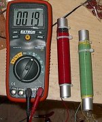
Self made, non-inductive high power resistors:
Attachments
- Status
- This old topic is closed. If you want to reopen this topic, contact a moderator using the "Report Post" button.
- Home
- Loudspeakers
- Multi-Way
- Electrolytics sound fine