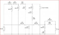
Ok well I thought I would list the crossover models I have come up with based on my measurements. Yes I still have the differences in drivers going on, and so this is a very preliminary crossover design. Once the enclosure is finished I plan to take some final measurements and make my final crossover value adjustments. Now that I have the ability, I'm going to modify the values of the left and right crossover in order to account for the driver differences to attempt to have them within 1-2db's of each other across the board. As it stands, this speaker is flat from around 500hz to 20khz at roughly +/- 1.5 db's, and the largest difference between two adjacent points is roughly 2 decibles. I designed this in speaker workshop, using ATB PC Pro and WT3 for measurements. I also must admit to taking cues from Orca's crossover design with these drivers, I used there LCR setup for the tweeter, but with slightly different values. The drivers are the Focal 6W 4254 and the tweeter is the TC120tdx, however if I do have a blown tweeter, that will probably have to change to the td5, and thus a change in crossover values again. Anyway, here is the schematic, take a look, let me know what you think.
Attachments
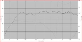
Here is the predicted response based on actual measured data from the speaker, but not in the final box (I used the FRD consortium tools to work that out for prediction purposes, but as I said, things will change when I do get the final enclosures done.
I will try and work up an enclosure drawing, but we are talking about basically a 2-way tower in a 1.75 cubic foot enclosure tuned to 38hz or so. My estimation for size is roughly 37"x9"x12" or something like that. The walls will be roughly 1.5" thick, and I'm hoping to play around with constrained layer walls, especially for the front. ATB PC Pro has an accelerometer, so I'm hoping to play around with measurements of the cabinet resonances to optimize until they are reduced as much as possible. My model also assumes the tweeter is offset roughly 1.5"s, but thats just a number I threw in, I will know better when I get working on the enclosure design.
I will try and work up an enclosure drawing, but we are talking about basically a 2-way tower in a 1.75 cubic foot enclosure tuned to 38hz or so. My estimation for size is roughly 37"x9"x12" or something like that. The walls will be roughly 1.5" thick, and I'm hoping to play around with constrained layer walls, especially for the front. ATB PC Pro has an accelerometer, so I'm hoping to play around with measurements of the cabinet resonances to optimize until they are reduced as much as possible. My model also assumes the tweeter is offset roughly 1.5"s, but thats just a number I threw in, I will know better when I get working on the enclosure design.
Attachments
Ah I just noticed the Baffle Step values aren't right. Consider those place holder's, but they probably will be more like .75mh to 1mh for the inductor and 5-8 ohms for the resistor. I think 8-10 ohms gives the best measurement, but it's too much baffle step, I don't want to lose that much efficiency, especially considering these will be used for both music and home theater.
I was hoping for some comments. Maybe I should have designed with some seas, peerless, or Scan-speak drivers, I think those are preferred around here.
In all seriousness though, I would love some feedback on the crossover. I'm fairly new to crossover design. Some of you will notice I'm even newer to speaker measurements. If anyone wants to comment on the values, I would love it.
I have another design I did as a three way, using a 10" woofer from Dayton Reference series. The response looks nice, but the inductor values were huge, and I was realizing just how much that crossover was going to cost me. That, and really the 6W 4311 is a better driver for midrange duties, its more efficient, has greater x-max, and a fairly similar response overall. I just did it cuz these are the drivers I have to work with right now.
Another idea I have had is a 3 way using a focal car audio 4" w-cone midrange driver. The reason would be more for center channel than the main speakers. If I have the 4" midrange, I then would have the ability to place the tweeter and midrange in a proper placement and have better response and dispersion. 5 1/5" 5W midbass could also work I suppose.
Are you playing with the same drivers? Please post or link to your drivers/specs (or new specs you have measured if you think they have changed). I am going to read your information. What kind of baffle are you using (size) for baffle step and how much. What do you think about the xover, I mean how you came to such a complex network. (Do you know) When you have a lot of components you will lose quality.
Inductor you make a bold claim to say, when you have a lot of components you lose quality. That is rather a debated topic. It's a tradeoff between frequency response, and the potential distortion that all the parts add. Keep in mind that really, at least in my opinion, most of the issues come from series components, rather than the parallel components. As for how I came to this design, its a standard 4th order design with an RLC trap on the tweeter and baffle step. I personally think that 4th order crossovers are required with these focal drivers, as the sandwhich cone of the midbass driver has some breakup thats best controlled with a steep slope. I'd rather not debate the merit of a complex crossover vs a simple crossover, as I feel that is more a religious debate than anything. I mean, I can't get a smooth response from simple 1st order crossovers, so I feel like I'm always trading good driver integration for efficiency. To combat the efficiency issue, I simply intend to use good quality inductors with suitably low DCR's.
I will post the driver information you are looking for later. Are you asking for my FRD and Impedance files? T/S parameters? Let me know.
I've not actually designed and built the enclosure (I will actually have it made for me, my current living conditions (apartment) dont allow room for many power tools anymore. Lets just say, for the sake of arguement, that the baffle will be roughly 9-10 inches wide, 35-40 inches tall, and have at least a 3/4" roundover. I'm looking into the cost of a 1" roundover bit for my router, which I think might be prefered. I used these numbers in the FRD consortium Baffle diffraction simulator. I intend to base actual baffle step numbers on measured data, not simulations though.
What specific driver files would you like, I have the original measured T/S and impedance files, I have traced and now measured FRD files, I have my simulated FRD files for baffle step, etc etc. Let me know. Hopefully by next weekend I will have anechoic measurements of the drivers done at the environmental testing lab here at Purdue, I'm just working out permission to remove the files from the facility when I'm done (necassary to actually use them I think).
What is it you think is so complex about this crossover, I think I could have made it far more complex. I could have built 5th order Bessel with impedance compensation (zobel), notch filters, and LCR traps, as well as baffle step. However, I would probably have an efficiency rating of 80db's, or expensive inductors the size of my head, and a price beyond need. To the point though, I think the designs from Humble Home Made Hifi, Troels Gravesen (sp?), and even Zaph are on par with mine for complexity, if not worse. I will say, it might be hard to read or follow that schematic. I haven't figured out how to lay things out so they don't look so messy.
pjpoes said:I intend to base actual baffle step numbers on measured data, not simulations though.
We shall wait then.
ITMT how much was BSC for Xlbaffle software (I presume?, I am going to try today for the first time. I used Svante' Basta! and Edge).
Well I have to be honest, I use BSC's results as a starting point, and adjust till it looks good. At least thats been my method in the past. I usually design far more speakers than I actually build, which is problematic in learning how much BSC I really need. However, I was told once that most of these softwares look for too much BSC, that while it may give the flattest response, it has the problem of too much efficiency loss. I believe that I came up with a target frequency of something like 516hz and I think it suggested 12db's or something like that. I ended up adjusting it for 3 db's. I actually am using the BSC values that Orca's designer Alan came up with, slightly adjusted for my slightly narrower baffle. He is of the similar mindset that 12db's of adjustment is just ridiculous.
If someone can prove me wrong on this, please do, but so far at least, my small collection of production crossovers are yet to find one with any BSC at all. I don't have the crossover designs from some very expensive and well designed speakers such as Revel Ultima Salons, but I do have the crossovers schematic (roughly) for the JmLabs Mini Utopia, which has no BSC. I also had a look at the crossover in a Magico Mini at an audio show, and I didn't see anything that implied it had BSC either. In counting the parts and looking at orientation, it would have to have a 12db per octave crossover on the midbass and 6db on the tweeter to have had BSC, or he doesn't use inductors in his? While I don't really know what the point of this is, I find it interesting that the manufacturers choose not to include BSC. I mean, whats that mean exactly, that its not important. When they weighed the cost benefit, it apparently didn't make the list. Does it provide for improved Fr response in room, or just change the character? I've done no in room measurements with and without to see, but its an interesting thought.
If someone can prove me wrong on this, please do, but so far at least, my small collection of production crossovers are yet to find one with any BSC at all. I don't have the crossover designs from some very expensive and well designed speakers such as Revel Ultima Salons, but I do have the crossovers schematic (roughly) for the JmLabs Mini Utopia, which has no BSC. I also had a look at the crossover in a Magico Mini at an audio show, and I didn't see anything that implied it had BSC either. In counting the parts and looking at orientation, it would have to have a 12db per octave crossover on the midbass and 6db on the tweeter to have had BSC, or he doesn't use inductors in his? While I don't really know what the point of this is, I find it interesting that the manufacturers choose not to include BSC. I mean, whats that mean exactly, that its not important. When they weighed the cost benefit, it apparently didn't make the list. Does it provide for improved Fr response in room, or just change the character? I've done no in room measurements with and without to see, but its an interesting thought.
pjpoes said:... While I don't really know what the point of this is, I find it interesting that the manufacturers choose not to include BSC. I mean, whats that mean exactly, that its not important. When they weighed the cost benefit, it apparently didn't make the list. Does it provide for improved Fr response in room, or just change the character? I've done no in room measurements with and without to see, but its an interesting thought.
If you don't apply BSC is because you are helping with a woofer or sub, a little (Focal with some BSC) or a lot in this case with no BSC at all. Of course the output comes up in the same amount that is not attenuated. Maybe that's why those commercial speakers you mention.
Yours I suppose is a Midbass 6W 4254 - Rubber surround fs=42.85Hz.
I read about another midrange Audiom 6 WM with coated fabric and fs=116.9Hz.
ps. Madisound was also doing reconing of Focal drivers.
http://www.orcadesign.com/
Attachments
the sheet you posted is for the driver I have. Maybe you are better at tracing than I, but I don't recomend tracing that driver to check my crossover. Well, I shouldn't say that, I have traced impedance and fr files for the driver, and ran my crossover, its really close. Anyway, Let me my Zma file, thats the part that will be the most off. If you do trace the Frd, check very carefully that the peak is in the right place.
Yeah I kept labeling the driver 6W in my schematics cuz its shorter, but 6W is an actual driver, and not what I have. Actually, I don't really like the 6W either, very hard to work with.
As for BSC not being used because of a subwoofer, if you think about the alternative, a 2.5 way, then really a subwoofer can't be used for BSC. BSC has to come in too high for that, around 500hz or more, and that would make the subwoofer too directional. I think they choose not to use it because they don't feel its important in their designs, that or they use alternative methods that I an unaware of. Like I said, I do typically add BSC, as I like what it does, but have often wondered why so many manufacturers choose not to. If I could get a second set of the 4254's, I might consider a 2.5 way design (you can use a 1st or 2nd order crossover in this case) for BSC instead, as it would allow me to save some efficiency.
Oh forgot to add, Orca did finally get back to me, and I can get replacement domes for the tweeters, so its possible. None the less, I found out what the problem was. They were "damaged" in shipping, the coils were out of alignment. I dismantled them and found ferrofluid on the back of one of the domes. I cleaned the two domes, carefully reassembled them, used a cross hatch torquing method, and finished final reassembly. Using this method I was able to fix the problem. The domes both measure around .15 mh of inductance, around 6.8 ohms dcr, and have an fs at around 1000hz. The impedance rise looks normal and smooth now, everything seems good. The midbass drivers needed to be worked in a little, and then securely clamped durring testing. After my testing in the lab I realized that you really should test the drivers in a near anechoic room with somewhat controlled atmospheric conditions. The lab I was in used the 12'x12' anechoic chamber with controlled temperature, humidity, etc. The driver was securely mounted by its motor assembly area. Through this method, I managed roughly equally good results with all the methods of testing. The Fs still is too high compared to that spec sheet you show, but its close enough. The Fs is like 44hz and 46hz for each of the drivers respectivly, and thus my Vas and mms are a little off, but I've been told its fine, average the two if it makes me feel better.
About the high order xover read what I've said to Simon.
http://www.diyaudio.com/forums/showthread.php?postid=1505718#post1505718
unless you go the Duelund (DK) way with extremely expensive parts that you can't afford.
As soon as you have a graph for tweeter output in frequency, post it (only found one for the Focal TC120td).
http://www.diyaudio.com/forums/showthread.php?postid=1505718#post1505718
unless you go the Duelund (DK) way with extremely expensive parts that you can't afford.
As soon as you have a graph for tweeter output in frequency, post it (only found one for the Focal TC120td).
In fact FOCAL 6 W 4254 shows a high BSC (~9dB) between 100Hz and 1KHz. As you said earlier about a 12dB BSC, not that much but very close, for the driver to be used as a mid-woofer. Unless you add a subwoofer. I will re-check with Edge/Basta! software next to confirm.
Attachments
At 9" cabinet width, part of what looks like baffle step is actually a diffraction peak centered at around 1100 Hz with a slope that happens to blend into the baffle step slope.
Modeling a 9" wide baffle in The Edge showed slighty higher peaking than measured in cabinets 10" wide and 1.25" roundovers. but the center frequency matched. If you want to cross high you'll need to notch that out, or deal with a 3-4 dB hole in the response above 1300 or so to the crossover.
I used the same drivers (actually -TD5), but used a high order elliptical active filter (~LR8 initial rolloff) to cross at 1400 Hz. This sounds much better to my ears than the original 2400 Hz LR4 crossover with appropriate notch filters.
As an M-T it feels like the single woofer trying to get down to 80 Hz is the limiting factor at high levels rather than the tweeter being pushed too hard. I haven't measured distortion, though.
Hope this helps.
FOCAL 6 W 4254-BSC on Edge @570-600mm/24"
We can look at a BSC of ~7dB in this case.
Not if you take advantage of that in your xover, roll off. You don't say how high. It seems that at 2KHz it's clear.
We can look at a BSC of ~7dB in this case.
BobEllis said:Modeling a 9" wide baffle in The Edge showed slighty higher peaking than measured in cabinets 10" wide and 1.25" roundovers. but the center frequency matched. If you want to cross high you'll need to notch that out, or deal with a 3-4 dB hole in the response above 1300 or so to the crossover.
Not if you take advantage of that in your xover, roll off. You don't say how high. It seems that at 2KHz it's clear.
Attachments
Inductor said:Not if you take advantage of that in your xover, roll off. You don't say how high. It seems that at 2KHz it's clear.
Right- I think that's part of the reason why my high order low XO version sounds better than trying to cross to that curve at 2500 like the Focal/JMLab Micro Utopia I was semi-cloning.
The peak extends a little higher than I remembered it, but it has been years since I looked at it.
You can make a passive Cauer-Elliptic filter - See the HT Guide diy forum for some examples of the topology. It's typically one part per section more than a LR4 XO, so they tend to be expensive. They can be modeled in Speakare Workshop.
Actively it is a fourth order filter with a notch about an octave outside the passband to get an 8th order initial rolloff. The response bounces back up to net out at 4th order, but if you keep the bounce >50db down, life is good.
PJPOES -
As for commercial speakers not having BSC, did you know that you can impliment BSC without adding components? Model a textbook crossover and then double the low pass section's first inductor value. You'll see a shelving effect.
The exact increase you need to match the compensation you want varies by application. Other component values will need to be changed to maintain the same XO frequency and corner shape but you'll get the idea. You can reduce your component count and increase your net sensitivity (the separate BSC inductor will add its own losses, not just distortion) while saving money.
And, yes, you'll want BSC if you plan to have your speakers out in the room. The closer they are placed to the rear wall the less you'll need, but even backs against the wall you will usually need some. Without it, your speakers will sound bass shy and thin in the lower midrange.
Thanks guys, I would like to make clear though, I have no real problems with BSC, I just wondered why I didn't see it more in commercial designs. Maybe they do as you say Bob, but I have, as I said, some schematics that have no BSC. My JmLabs Electra 905's have no BSC, I can show you the schematic sometime if you want. Those were what, like 2200 dollars a pair new, and I consider them bookshelf.
By the way, the enclosure isn't planned yet, I have drivers, some measurements, and some drawings. As I mentioned, I don't have room right now to build my own, so I must rely on others to build them for me. I'm awaiting a quote on a few designs we came up with. This was really meant as a temporary holdover, and chance to play with the midbass drivers, until I can afford and have time to do my final penultimate design. Or should I say, start to severe and expensive DIY nervosa. I've been building some speakers using the Scan-speaker revelator midbass drivers and various tweeters, and I keep thinking I would like try this with the Focal tweeter. Only thing is, I don't feel like the midbass is clearly better than the focals, its just different. Better bass, better dynamics, I think it has lower measured distortion, but it just doesn't sound as clean to me. More importantly though, I think nothing does microdynamics like focal drivers, which is why I like them so much myself.
Bob I would be curious to know what you think of the crossover. Sounds like you feel a 10" wide baffle would be good, a different BSC scheme to match, but otherwise, seem ok? I mean, there are only so many 4th order setups you can do really. I heard you mention LR4 a few times, I didn't model those after LR4, but after tweaking the slopes I may have inadvertently ended up at that. I think they match Butterworth better though. They are also steeper than 4th order. The resistor I have from inductor to ground and cap to ground removes crud in the crossover region and increases the slope slightly.
You've gone the extra mile with the tweter notch. I have tried with and without and have no clear preference.
As for the BSC in your 1st post, the norm is to place the L//R on the source side of the filter. As it is now, you've added a bit of variable impedance to your filter load.
You know by now, I'd cross it lower.")
You may end up with a 2nd or 3rd order electrical filter and get to a fourth order electrical rolloff.
As for the BSC in your 1st post, the norm is to place the L//R on the source side of the filter. As it is now, you've added a bit of variable impedance to your filter load.
You know by now, I'd cross it lower.
You may end up with a 2nd or 3rd order electrical filter and get to a fourth order electrical rolloff.
- Status
- This old topic is closed. If you want to reopen this topic, contact a moderator using the "Report Post" button.
- Home
- Loudspeakers
- Multi-Way
- Focal tower speaker Project