MaVo said:Dr Geddes,
could you answer a question about the mouth termination of an OS waveguide?
Your speakers waveguides have a mouth flare after the part with the constant wall angle, which looks like a circular shape. It doesnt seem to be part of what the OS equation gives. You stated earlier in this thread, that the intention of this is to attenuate diffraction and mouth reflection.
My question is: How do i determine the correct shape for this mouth termination?
Again, this has been discussed so many times before.
First, there is no "constant wall angle" part of an OS waveguide. It is constantly changing but by ever smaller amounts. The mouth treatment is not part of the OS equations. The mouth radius should be as large as practicable (a radius larger than 1/4 wavelength at the lowest frequency it is not necessary). So a rule of thumb is to target a radius of 1/4 lamda - which is hard to do.
Thanks - and sorry if i made you repeat yourself - i searched for some hours and found nothing on this topic in this forum.
gedlee said:I don't follow. How does one make a coax where the waveguide is about the same size as the woofer?
Generally something like this
An externally hosted image should be here but it was not working when we last tested it.
Although, as I noted, if the woofer becomes a mid with almost no excursion, the horn can look like this
The Gradient is a coax Earl. I've mentioned this to you before.gedlee said:
Duke did no such test that I am aware of. What are you referring to? The test that Duke and I did with the Summas had no coax.
Summa vs Gradient coax
cheers,
AJ
gedlee said:This has clearly been your assumption, but it is not correct. It depends on where the size of the horn lies relative to the wavelengths. A narrower vertical coverage horn has a narrower vertical dimension. Hence it will be diffraction limited to a far higher frequency than a round one. You are making assumptions for simplicity that are simply not correct. The narrower coverage horn COULD have a wider pattern at the lower frequencies than the wider coverage horn. It all depends on relative sizes as I said before.
I am not arm waving or working on assumptions, so please stop using phases like that to describe my position. I am basing all my comments on observations from actual measurements of physical devices.
The widening of the pattern from mouth diffraction at low frequency is well known. The frequency where pattern control begins to take the shape of the wall angle is also pretty well studied. Neither of us disagree on how pattern control in a horn works.
If I take an axisymmetrical horn with 90 degree pattern and compare it to a asymmetrical horn with 90 degree horizontal and 40 degree vertical pattern, at high frequency, both have similar horizontal coverage but the asymmetrical horn delivers less energy at wide vertical patterns. This is not in dispute, it is easy to see in measurements. So there is the first point, at high frequencies, the 90x40 horn delivers less energy at tall vertical angles.
Now take these two horns and measure the vertical beamwidth as frequency drops. The pattern remains constant 90 degrees from the axisymmetrical horn down to some frequency where it begins to lose pattern control. Usually pattern narrows briefly before widening, but ultimately, it widens up because of mouth diffraction. The asymmetrical horn with small vertical dimension loses pattern control at a higher frequency. This is the part you are talking about, and here, we agree.
The question should be, at what point does the asymmetrical horn's vertical beamwidth widen to 90 degrees, making it equal to the 90 degree round horn? How wide is the asymmetrical horn in the vertical in the crossover region and just above, and how does it compare to an axisymmetrical horn. Now I ask you, have you looked? Find some of these 90x40 horns and look at their vertical beamwidth around 2kHz - 3kHz to see. The vertical pattern is less than 90 degrees.
To summarize, there is no question that the vertical beamwidth through the passband of a 90x40 horn is smaller than an asymmetrical 90 degree horn. The question for you, it seems, is what frequency does the vertical pattern widen to exceed 90 degrees. I submit to you it is a relatively easy design choice to make sure that the horn is appropriate for the job, picking one that has dimensions which will allow it to provide enough vertical control to have beamwidth of less than 90 degrees above the crossover point. Ideally, it would be much less.
AJinFLA said:Gradient is a coax Earl. I've mentioned this to you before.
I see what you mean now, I was thinking more along the lines of a horn loaded device, not what you are showing here.
Yes, if you are going to do a coax then using the cone as the waveguide extension is the best way. But its still going to have problems when compared to the way I do waveguides. There is a poor mouth termination and there isn't any place to put the foam.
Again, if size is critical this approach is very good, but I'd still take the vertical holes at the crossover to the problems created by the coax.
MaVo said:Thanks - and sorry if i made you repeat yourself - i searched for some hours and found nothing on this topic in this forum.
Yes, well that does happen. Maybe a new thread? Then we can start clean and get to the meat before the whole thing gets dilluted into oblivion.
Wayne Parham said:The widening of the pattern from mouth diffraction at low frequency is well known. The frequency where pattern control begins to take the shape of the wall angle is also pretty well studied. Neither of us disagree on how pattern control in a horn works.
If I take an axisymmetrical horn with 90 degree pattern and compare it to a asymmetrical horn with 90 degree horizontal and 40 degree vertical pattern, at high frequency, both have similar horizontal coverage but the asymmetrical horn delivers less energy at wide vertical patterns. This is not in dispute, it is easy to see in measurements. So there is the first point, at high frequencies, the 90x40 horn delivers less energy at tall vertical angles.
The question should be, at what point does the asymmetrical horn's vertical beamwidth widen to 90 degrees, making it equal to the 90 degree round horn? How wide is the asymmetrical horn in the vertical in the crossover region and just above, and how does it compare to an axisymmetrical horn. Now I ask you, have you looked? Find some of these 90x40 horns and look at their vertical beamwidth around 2kHz - 3kHz to see. The vertical pattern is less than 90 degrees.
To summarize, there is no question that the vertical beamwidth through the passband of a 90x40 horn is smaller than an asymmetrical 90 degree horn. The question for you, it seems, is what frequency does the vertical pattern widen to exceed 90 degrees. I submit to you it is a relatively easy design choice to make sure that the horn is appropriate for the job, picking one that has dimensions which will allow it to provide enough vertical control to have beamwidth of less than 90 degrees above the crossover point. Ideally, it would be much less.
Your argument is getting more coherent because now you are considering the details.
First, this discussion is about what happens at the crossover, not in the passband. The crossover is the low end of the waveguides design so what it does in the passband is not pertinent to this discussion.
Now IF the elliptical waveguide had the same vertical dimension as the circular waveguide THEN your argument has some merit. But this is unrealistic in practice as the elliptical is now twice as wide as the circular one. If the widths are made the same then the elliptical one is now half as tall and at the low end - at the crossover - its coverage pattern could well be WIDER than the circular horn because its dimension is so much smaller (lose of pattern control). Thus, this "detail" defeats your argument unless you make some other compromises. In my investigations this has not worked out so well.
I HAVE studied this which is why I know that it isn't as simple as you expressed in the first place. And you STILL haven't shown any data to support you position.
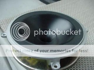
This looks like a very clean approach. These are Tannoy drivers? I would be interesting to get hold of one of these to play around with. Especially playing around with the center horn termination.AJinFLA said:
Generally something like this
An externally hosted image should be here but it was not working when we last tested it.
Although, as I noted, if the woofer becomes a mid with almost no excursion, the horn can look like this
The Gradient is a coax Earl. I've mentioned this to you before.
Summa vs Gradient coax
cheers,
AJ
gedlee said:
Yes, well that does happen. Maybe a new thread? Then we can start clean and get to the meat before the whole thing gets dilluted into oblivion.
DiyAudio does have a (practically unused) Wiki section, instead of a "encyclopedia article" format perhaps someone could collect/edit posts from a few threads, with post contributers clarifying their points in the new context
http://www.diyaudio.com/wiki/index.php?page=diyAudioWiki
I know its supposed to "just work out" in a Wiki with anyone editing anything but I could see agreeing on "thread summary" rule strictly attributing content to the post's authors with a strong preference for only original authors editing their respective quoted post' content
I would try to use the Wiki if images could be "inlined" - engineering discussions without drawings/schematics/graphs is pretty lame
gedlee said:Your argument is getting more coherent because now you are considering the details.
First, this discussion is about what happens at the crossover, not in the passband. The crossover is the low end of the waveguides design so what it does in the passband is not pertinent to this discussion.
Now IF the elliptical waveguide had the same vertical dimension as the circular waveguide THEN your argument has some merit. But this is unrealistic in practice as the elliptical is now twice as wide as the circular one. If the widths are made the same then the elliptical one is now half as tall and at the low end - at the crossover - its coverage pattern could well be WIDER than the circular horn because its dimension is so much smaller (lose of pattern control). Thus, this "detail" defeats your argument unless you make some other compromises. In my investigations this has not worked out so well.
I HAVE studied this which is why I know that it isn't as simple as you expressed in the first place. And you STILL haven't shown any data to support you position.
No, this discussion is not limited to what happens in the crossover region. The nulls are limited to that region, so their position can be found knowing the range of overlap frequencies, and the phase and position of the sound sources. But that isn't all that is important to me.
My point is, and always has been, that I suggest matching the horn's vertical pattern with the null angle. This isn't just because I'm trying to limit the nulls and lobes outside the nulls, although it would be great if the horn had pattern control enough to do that. It is also because I want the pattern above the crossover region to remain narrow, within the angle defined by the nulls.
What I'd like to see in my loudspeakers, is for the vertical pattern to remain narrow above the crossover point, where the nulls define the shape of the pattern. Through the crossover, the nulls set the pattern. Above the crossover, the horn sets the pattern. I'd like it to remain narrow, to equal the null angle as much as possible.
What you're talking about is the nulls, themselves. It would be great to limit the beamwidth through the crossover range too, because this would reduce the lobes outside the nulls. In fact, if beamwidth were smaller than the null angle, the nulls wouldn't even exist. But the problem here isn't limited to just the directivity of the horn; The midwoofer also has a relatively wide vertical pattern, around 90 degrees through the crossover band.
So again, my position is that I prefer the pattern at HF to be narrow. This isn't about reducing the nulls. It's about reducing the pattern at frequencies above the nulls, where they no longer exist. My design philosophy is to match the vertical pattern to the null angle, so that response at large angles doesn't rise at HF.
This approach makes the nulls less prononounced, in contrast with the horn's passband amplitude. My measurements show approximately 6dB average reduction in amplitude at the null angle through the crossover range. They also show approximately 6dB reduction from horn directivity at HF. That's a match, and that's what I like to see.
I've shown my vertical response curves. Let's examine yours for comparison.
jcx said:engineering discussions without drawings/schematics/graphs is pretty lame
This is of course the root of a lot of problems. Engineers usually need to see the "paperwork" to fully understand something, but then a lot of people don't fully understand the paperwork - for those rare occasions where some documentation is actually present. This is the reason that I balk on so many in-depth questions. Its just not reasonable to do these kinds of discussions in a casual forum like this.
This is "Geddes on Waveguides" and I posted my Chapter on Waveguides for all to read. Lets see how many questions I get from that. (A few so far, but not many. I didn't think that it was that clear😀 )
Wayne Parham said:
No, this discussion is not limited to what happens in the crossover region.
... This isn't about reducing the nulls.
I've shown my vertical response curves. Let's examine yours for comparison.
We arn't talking about the same things, and somewhere along the line you changed the discussion because to me it was only ever about the effect of the nulls at the crossover. I have not been discusing the rest of the frequency range. Sure a narrower vertical pattern (if its well controlled) above the crossover would be desirable if it didn't make more problems with the crossover than these advantages offer. But I am afraid that it does.
My data has long been available on my site. Yours are very course and quite limited in angle. I'd like to see a higher res. set of data.
I have a few issues, but I'd rather digest the chapter a bit more before I address them. But I do agree it's hard to get into much detail without the paperwork. Additionally, approach to speaker design is diverted. For example, lots of direct radiator models assume rigid diaphragms which in reality is far more complicated. We also face the same issue with wave guides and enclosures. I doubt that anyone will integrate all this knowlege to generate the magnitude of how each aspect effects the quality of reproduction.gedlee said:
This is of course the root of a lot of problems. Engineers usually need to see the "paperwork" to fully understand something, but then a lot of people don't fully understand the paperwork - for those rare occasions where some documentation is actually present. This is the reason that I balk on so many in-depth questions. Its just not reasonable to do these kinds of discussions in a casual forum like this.
This is "Geddes on Waveguides" and I posted my Chapter on Waveguides for all to read. Lets see how many questions I get from that. (A few so far, but not many. I didn't think that it was that clear😀 )
gedlee said:We arn't talking about the same things, and somewhere along the line you changed the discussion because to me it was only ever about the effect of the nulls at the crossover...
My position has never changed, and my descriptions of this idea have never changed either. Frankly, I was beginning to become afraid that people would say I'm repeating myself over and over again. To you, maybe it was just about the nulls because that is a critical part - the null angle. But to me, it has always been about matching the horn's vertical pattern to the null angle. I like to match the horn's horizontal beamwidth to match the device being crossed from, and I like to match the horn's vertical beamwidth to the null angle.
gedlee said:My data has long been available on my site. Yours are very course and quite limited in angle. I'd like to see a higher res. set of data.
I haven't seen charts of vertical response off-axis, only horizontal. Please give a link if you have one.
Also, your charts all seem to be smoothed to 1/3 resolution. Mine are all unsmoothed and much more revealing. My measurements are anechoic, all the way down to 20Hz. I'm assuming yours are pseudo-anechoic, because they don't go down very low. I measure every 10 degrees, you do 7.5 degrees. That's the only area where your measurements show finer resolution than mine. I'd like to see anechoic measurements of your speakers with no smoothing applied, and I'd like to see vertical off-axis charts.
I think Wayne is using sine wave type signals as source, and Earl is probably using MLS type signal as souce. Is this understanding correct?
Chapter 6
Dr. Geddes,
Since Huygen¡¦s principle is mentioned in the book, it seems that based on this, in a traditional horn, the acoustic center is continously changing due to diffraction, and that depending on shape of final wave front, AC could actually be different on-axis versus off-axis. Do I interpret this currectly? If not, could you elaborate a bit more on this?
Is your idea of HOMs due to the horn/guide based mainly on understanding that based on Huygen¡¦s principle, the diffraction reflection is the source of HOMs?
soongsc said:I think Wayne is using sine wave type signals as source, and Earl is probably using MLS type signal as souce. Is this understanding correct?
I measure with several different signal types, to try and look at the system from lots of angles. I also measure at different power levels in some applications, to see the shifts that result from high excursion and high temperature.
During development, I use a variety of tools, including Spice models for crossovers and the Smith and Larson system, which has the capability to use sines, stepped sines, noise, MLS, impulse and chirp signals. It also has gating capability for pseudo-anechoic measurements.
The other system I use for acoustic measurements is LMS. It uses stepped sines for measurement and is capable of doing pseudo-anechoic measurements, but I usually use it outdoors to measure true anechoic response.
I have been using LMS for quite some time, and have only recently started using the S&L system. Keith Larson, the chief developer, is excellent both in terms of technical knowledge and being pleasant to be around. Not only has he been helpful showing me around the system, but has been outstanding in making updates for future enhancement. I plan to use the S&L system much more in the future.
Both LMS and S&L are very capable, but I think it is safe to say that LMS is more mature. In fact, it's probably one of the most mature systems in use. But the Smith and Larson system is nice too, and I look forward to doing more with it than just the Spice simulations and initial acoustic measurements.
this has a few measurements of spl at the mouth of 2 horns, shows axisymetic radial modes and more complex modes ~p60+
digital.library.adelaide.edu.au/dspace/bitstream/2440/41350/3/02chapters1-4.pdf
I see Morgans' work has been mentioned on diyAudio:
http://www.diyaudio.com/forums/showthread.php?postid=1550742#post1550742
I'd look at the other refs if my DSL were working right now
digital.library.adelaide.edu.au/dspace/bitstream/2440/41350/3/02chapters1-4.pdf
I see Morgans' work has been mentioned on diyAudio:
http://www.diyaudio.com/forums/showthread.php?postid=1550742#post1550742
I'd look at the other refs if my DSL were working right now
I did a similar post to this but I somehow got it in a topic called "beyond the Ariel"
Any way what I observed was that it is entirely within the bounds of possibility that the author of the university of Adelaide paper came to his conclusions quite independently and did not read the Geddes book, and if he did and took material from it and did not mention it, he is guilty of plagiarism, not an accusation I would make lightly.
It should also be obvious that if the duct wall has an increasing slope the the non parallel wavefronts this produces are constantly adding energy to the evanescent field by scattering, and that these waves will propagate should the local cut off frequency become equal to the evanescent wave frequency.
rcw
See beyond ariel thread post 4131 and 4147
http://www.diyaudio.com/forums/showthread.php?postid=1552329#post1552329
http://www.diyaudio.com/forums/showthread.php?postid=1552329#post1552329
- Home
- Loudspeakers
- Multi-Way
- Geddes on Waveguides