Well, we may be a bit slow but we are not all engineers or have university degrees
point is that not everything in here is worth reading so sometimes important things does slip through unread
or somtimes we may gain interest in things that we overlooked ealier
This forum can be difficult and often requires a lot of patience
point is that not everything in here is worth reading so sometimes important things does slip through unread
or somtimes we may gain interest in things that we overlooked ealier
This forum can be difficult and often requires a lot of patience
WithTarragon said:
The threads are long, they go off topic, and the nuggets of science and engineering unfortunately get lumped in with the uneducated opinions and speculation.
From both fronts. Experts can has uneducated opinions, indulge in speculation or be flat out wrong sometimes too. Misinformation comes from all sources, not just us ignorant DIYers.
Sheldon said:Calculations for the OS waveguide profile can be found here: http://mywebsite.bigpond.com/dmcbean/
Then you have to figure out a way to construct it. The minimal tooling approach for a single pair is probably to make it by laminating successively larger circles, each representing a point on the curve. Then, *integrate the layers* with a filler such as automotive body filler and sand carefully, especially the throat region. The driver throat should be matched within a fraction of a millimeter to the horn opening.
Sheldon
I posted instructions on how to make a waveguide here:
http://www.htguide.com/forum/showthread.php4?t=22137
I posted a spreadsheet which you can use in conjunction with my instructions here:
http://spreadsheets.google.com/ccc?key=p4iluSrYmufEXz-LDVHlIIw&hl=en
Patrick Bateman said:
I posted instructions on how to make a waveguide here:
http://www.htguide.com/forum/showthread.php4?t=22137
I posted a spreadsheet which you can use in conjunction with my instructions here:
http://spreadsheets.google.com/ccc?key=p4iluSrYmufEXz-LDVHlIIw&hl=en
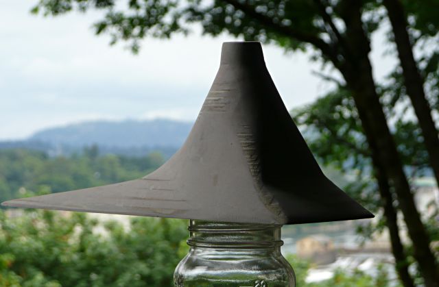
If you don't want to do the math, here's a way to make a crude waveguide. It's not as perfect as using a computer, but it's faster. These days I take my sweet time, since my expectations are higher than they were a few years ago.
Here is how you can do it.
Step 1 - Get a compression driver.
I'd recommend B&C DE25. About $120 at Parts Express.
Step 2 - Do the Math.
Easiest waveguide to build is a conical waveguide. It's not as mathematically perfect as oblate spheroidal, but it's easy to build. A waveguide with a mouth that's 15" in diameter is 7.5" deep if it has a coverage angle of ninety degrees. You can build that simply with cardboard. Basically you glue together ten pieces of cardboard to approximate the shape of a cone. Each triangle measures 4.712" at the bottom, with a height of 10.645", and the sides are 10.904" each. The angles are 25, 77 1/2, and 77 1/2. If you want to make something more permanent, you could make them out of plywood. I prefer cardboard, because I fiberglass mine.
Step 3 - Turn your cone into a horn.
This is the easy part. Cut out a circle about 5" in diameter. This will mate to your compression driver. Cut a 1" hole in the center of your 5" circle. Then hack off the top of your cone, so that there's a 1" hole in it. Then glue the cone to your 5" circle. You now have a very primitive conical waveguide.
Step 4 - Glass It.
If it were me, I would glass the shape, build it up with foam, etc... I basically make these the same way you'd make a surfboard. Fiberglass on the surface, foam in the center, and another layer of glass on the outside. Very strong. But you don't have to do this; if you're just messing around, even the cardboard waveguide is functional. Weak, but functional.
Step 5 - Measure It.
The great thing about a waveguide is that it does not 'beam.' However, the respone falls off in the top octaves. So before you do any listening, get out the measurement gear, and come up with a xover or a filter that gives you flat response. Otherwise, your new conical waveguide will not sound right.
Step 6 - Tweaks
Once you've spent an hour on this, you'll want to know how to make it better. The first thing I would do is baffle the waveguide, then radius the point where the mouth meets the baffle. If you're using fiberglass, this is easy. Pay very close attention to where the throat meets the compression driver; this is critical too.
Hope this helps!
Variac said:I would very much like to see posts that give examples of a particular section that could be used to make a particular waveguide- and some examples of waveguides that members have made.. and comments on their sound..
The waveguides I'm building currently are for my car. So they deviate from OS quite a bit. They *are* OS for the first inch or so. In a car I believe it makes sense to use a shape which blends with the interior; in my case these are going into the corners of my dash.

The thread about them is here:
http://www.diyaudio.com/forums/showthread.php?threadid=117537&goto=newpost
Hello gedlee,
i saw the yamaha vs. ESP15 measurements on your homepage and have two questions about them.
First one is simple: Are the measurements on page 10-13 also esp15? It says yamaha on the index page but somehow this doesnt seem to fit.
Second one (assuming the first question is answered with "yes"): On the vertical plots of the esp15 (pages 10-13), i can see an irregularity between about 500 and 1500hz. It seems to be a lobe around the crossover frequency, caused by woofer/waveguide distance - a deviation from the constant directivity of the speaker. Is this a problem and if it is, how do you treat it?
building OS
It would seem to me one way to fabricate an OS structure (short of casting up a negative from an existing one, i.e. reverse engineering) might be to inflate a baloon to the requisite cross sectional diameter, squash it a bit until its minor axis approaches the required profile, then use that as a negative mandrel to either press into loose plaster or lay-up fiberglass, etc, onto its surface to generate the finished piece.
Seems one could pop out many different cross section waveguides in a hurry for next to nothing using this method.
Gee.. maybe I'll try it...I'm curious to experience the enhanced clarity of suppressed HOM's, and may apply such a feature to my existing HT setup.
Thanks for the info, Earl...
John L.
It would seem to me one way to fabricate an OS structure (short of casting up a negative from an existing one, i.e. reverse engineering) might be to inflate a baloon to the requisite cross sectional diameter, squash it a bit until its minor axis approaches the required profile, then use that as a negative mandrel to either press into loose plaster or lay-up fiberglass, etc, onto its surface to generate the finished piece.
Seems one could pop out
many different cross section waveguides in a hurry for next to nothing using this method.Gee.. maybe I'll try it...I'm curious to experience the enhanced clarity of suppressed HOM's, and may apply such a feature to my existing HT setup.
Thanks for the info, Earl...
John L.
D OB G said:Earl, do you leave the "bug screens" on your DE250 drivers?
David
Ed LaFontaine said:I'd like to extend D OB G's question:
Earl, do you mate the waveguide directly to the DE250, or use some gasket material such as is provided by the manufacturer?
Actually both of those questions were answered further up the thread, but yes, I remove the screen as the foam does this same job. And Yes I retain the gasket material on the driver. These gaskets squeeze down to almost nothing.
MaVo said:Hello gedlee,
i saw the yamaha vs. ESP15 measurements on your homepage and have two questions about them.
First one is simple: Are the measurements on page 10-13 also esp15? It says yamaha on the index page but somehow this doesnt seem to fit.
Second one (assuming the first question is answered with "yes"): On the vertical plots of the esp15 (pages 10-13), i can see an irregularity between about 500 and 1500hz. It seems to be a lobe around the crossover frequency, caused by woofer/waveguide distance - a deviation from the constant directivity of the speaker. Is this a problem and if it is, how do you treat it?
Yes, that is mislabeled. The last four plots are all ESP15's. There are of course lobes in the vertical direction that result from the finite spacing of the drivers at the crossover. Of course it would be better not to have these lobes, but they are unavoidable with spaced drivers at the crossover. This is the argument for co-axial drivers as this problem does not then occur. However the small waveguide in a coaxial mount means that the polar response above the crossover in both the horizontal and the vertical direction is degraded. I think that the aberations in the vertical response at the crossver are by far the lessor evil.
This unavoidable situation is of course the reason why I say that all crossovers are bad, its just that some are not as bad as others. Minimizing crossovers is essential in a good design IMO.
Except that it doesn't minimize this effect. The transition/overlap is sharper but the phase change is greater and the net result ends up being different but no better. I have yet to see the application which really benefits from bi-amping (except the amp and crossover peoples profits).
However the small waveguide in a coaxial mount means that the polar response above the crossover in both the horizontal and the vertical direction is degraded
Earl
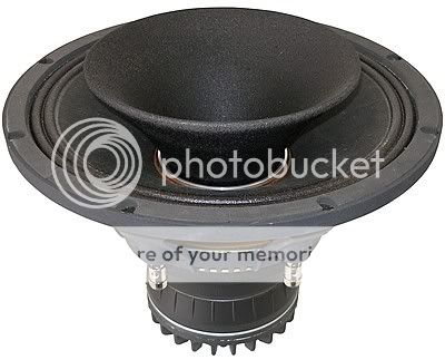
you are generalizing. There are certainly faded designs, like the horn of the Altec 604 , but recently, the manufacturers do take more care about the development of wave guides for their coaxes, and evolve. A good example is the new GPA Model 212-8A
http://www.greatplainsaudio.com/two_way.html
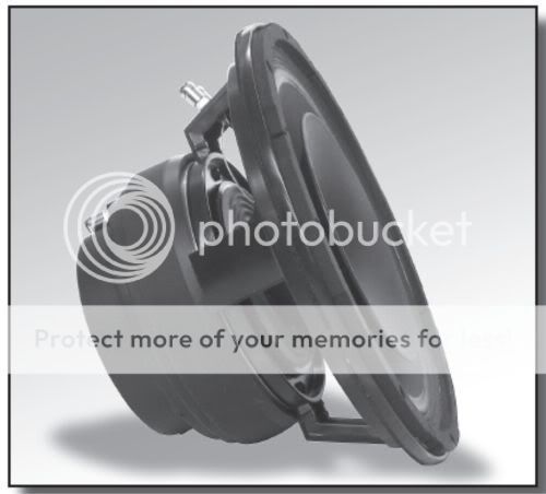
or the new triaxial BMS :
http://bmspro.com/
do you think these do have also a degraded polar response ?
actually, i don't understand, what you mean with " degraded polar response " ?
Angelo
Earl
you are generalizing. There are certainly faded designs, like the horn of the Altec 604 , but recently, the manufacturers do take more care about the development of wave guides for their coaxes, and evolve. A good example is the new GPA Model 212-8A
http://www.greatplainsaudio.com/two_way.html
or the new triaxial BMS :
http://bmspro.com/
do you think these do have also a degraded polar response ?
actually, i don't understand, what you mean with " degraded polar response " ?
Angelo
These may be "better" but they are still too small to have good polar response control (i.e. the response will not be constant directivity, independent of angle). A 10" waveguide is as small as I would ever use, a 12" is much better and it really takes about 15" of diameter to get the polar response to be well controlled down to about 1 kHz. There is also the unbaffled problem. A baffle or enclosure helps out the pattern control because there is less diffraction from the mouth.
Coax is a good solution in a very small package, I would use it myself in that situation, but it can never compete with a larger waveguide when size isn't a major motivator.
It is possible, and reasonable, to "generalize" about many things. In "general" a bigger waveguide will work better than a smaller one. So "generalizing" is not always a bad thing.
A bigger waveguide also allows for a larger foam plug which works better. Bigger is better.
Just by looking at data these openly publish, I would never try them.angeloitacare said:However the small waveguide in a coaxial mount means that the polar response above the crossover in both the horizontal and the vertical direction is degraded
Earl
you are generalizing. There are certainly faded designs, like the horn of the Altec 604 , but recently, the manufacturers do take more care about the development of wave guides for their coaxes, and evolve. A good example is the new GPA Model 212-8A
http://www.greatplainsaudio.com/two_way.html
or the new triaxial BMS :
http://bmspro.com/
do you think these do have also a degraded polar response ?
actually, i don't understand, what you mean with " degraded polar response " ?
Angelo
Matching directivity in the vertical and the horizontal
Suggestion: Use a tweeter horn with vertical directivity that matches the null angle. Said another way, use vertical spacing that matches the null angle to the tweeter's vertical coverage at HF. Dial in the crossover, tweeter and spacing to match the vertical pattern as best as possible for uniform response off-axis vertically as well as horizontally. This requires an asymmetrical horn, appropriate crossover and baffle spacing.
MaVo said:i saw the yamaha vs. ESP15 measurements on your homepage and have two questions about them.
First one is simple: Are the measurements on page 10-13 also esp15? It says yamaha on the index page but somehow this doesnt seem to fit.
Second one (assuming the first question is answered with "yes"): On the vertical plots of the esp15 (pages 10-13), i can see an irregularity between about 500 and 1500hz. It seems to be a lobe around the crossover frequency, caused by woofer/waveguide distance - a deviation from the constant directivity of the speaker. Is this a problem and if it is, how do you treat it?
Suggestion: Use a tweeter horn with vertical directivity that matches the null angle. Said another way, use vertical spacing that matches the null angle to the tweeter's vertical coverage at HF. Dial in the crossover, tweeter and spacing to match the vertical pattern as best as possible for uniform response off-axis vertically as well as horizontally. This requires an asymmetrical horn, appropriate crossover and baffle spacing.
- Home
- Loudspeakers
- Multi-Way
- Geddes on Waveguides