Hi,
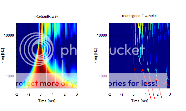
I plotted some wavelets from the RAdian/Azurahorn IR file.
Here's a 'CSD' equivalent wavelet:
Can I see consecutive reflections/diffractions?Either the driver, or the throat-mouth ping-pong?
- Elias
A little open cell foam, ala Geddes, might be worth a try.
Sheldon


Reflection off the lower bass cabinet is a possibility too.
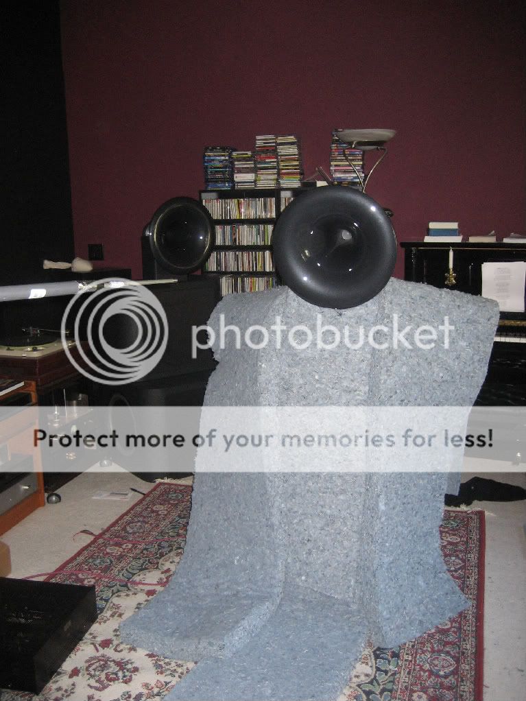
I expect there would be some. Measurement was done with the horn in position on top of the bass cabinets. I buried the bass cabinets in a mountain of Bonded Logic to attenuate the reflection, but that would have only .
During the test, I set the window at about 4.4 ms, which would shut out reflections from other objects in the room, such as the amp on the floor. But eventually they all get there!
BTW, the picture is a quick re-creation of the arrangement so you can see how things were placed. During the test, the mic was on axis with the driver.
Gary Dahl
Last edited:
If you are using a wm61 type electret condenser capsule, its normal connection method results in inverted signal.... I have attached the corresponding files in .pir and .wav formats. Vertical scale is arbitrary; the gain of my power amp hasn't been accounted for. The mic preamp doesn't invert phase, so it's probably the power amp, a Parasound HCA-1500A.
...
Gary Dahl
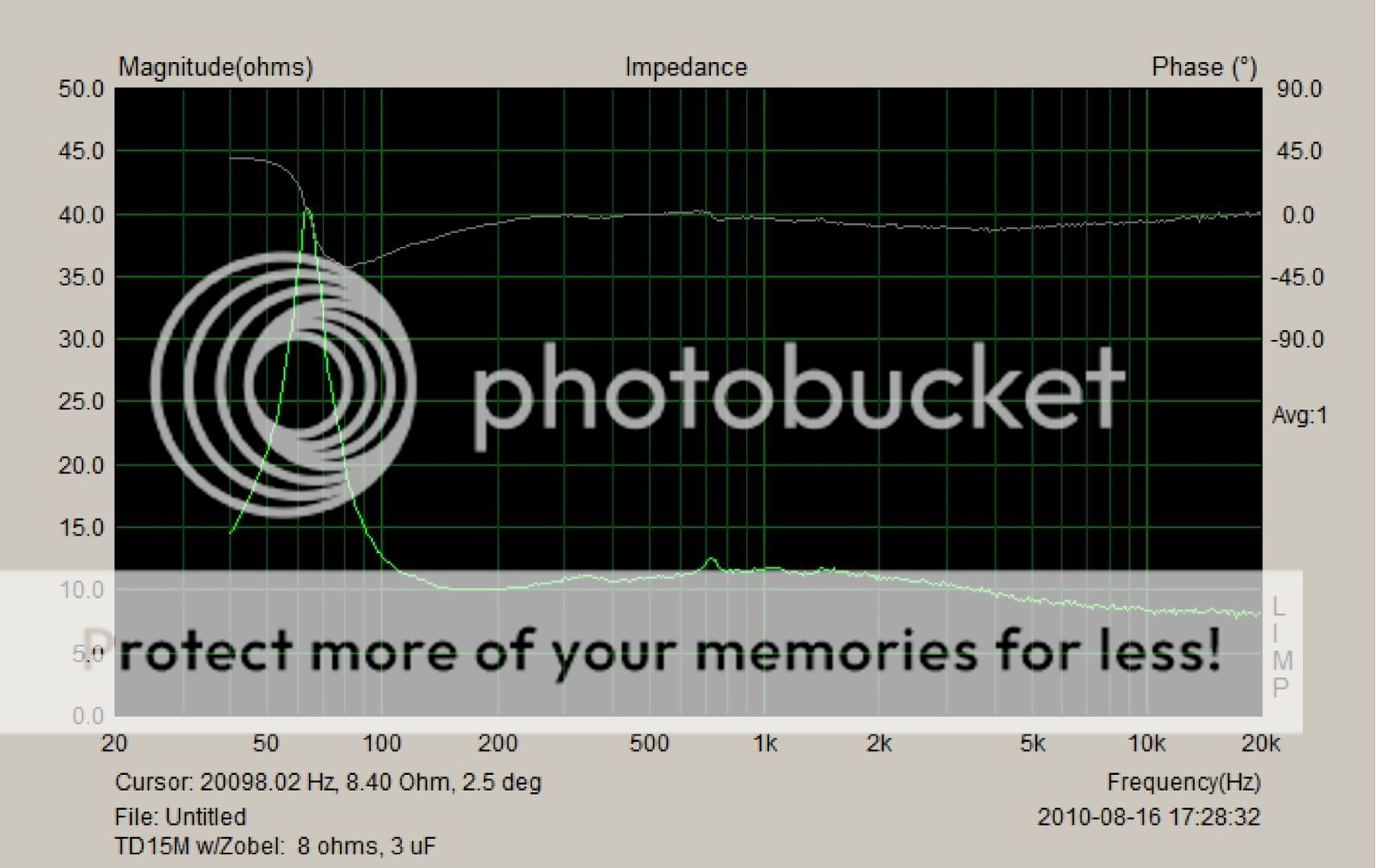
Started on the Zobel network for the TD15M this afternoon.
The calculator at mh-audio.nl - Calculations provided values of 8.25 ohms and 2.94 uF, so I began with 8 ohms and 3 uF:
Next, I tried it with a 2 uF cap. The green trace shows 3 uF; the yellow trace shows 2 uF:

Finally, I tried a 4 uF cap (yellow trace). The green trace is 2 uF.
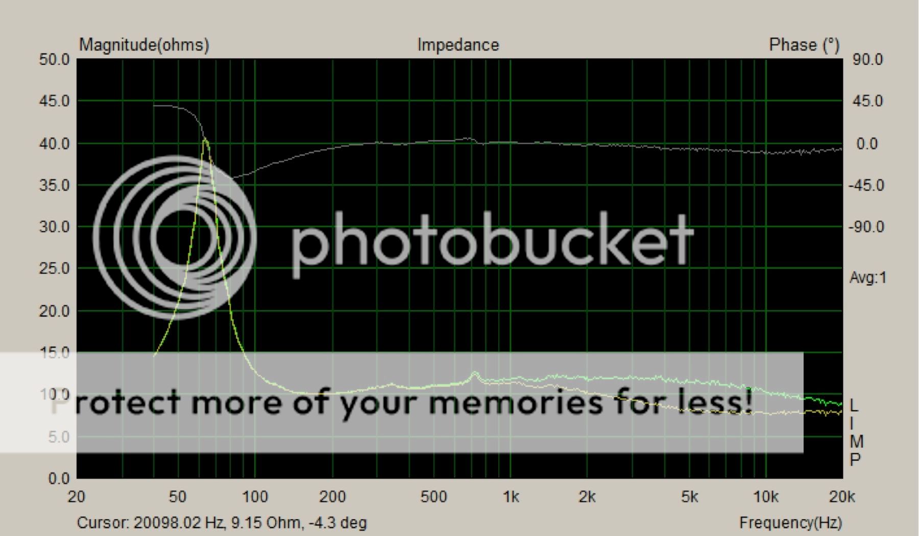
I wish I could overlay all three traces, but I couldn't get more than one overlay.
Comments? I think 2 uF looks best, but I'm new at this.
Gary Dahl
The calculator at mh-audio.nl - Calculations provided values of 8.25 ohms and 2.94 uF, so I began with 8 ohms and 3 uF:
Next, I tried it with a 2 uF cap. The green trace shows 3 uF; the yellow trace shows 2 uF:
Finally, I tried a 4 uF cap (yellow trace). The green trace is 2 uF.
I wish I could overlay all three traces, but I couldn't get more than one overlay.
Comments? I think 2 uF looks best, but I'm new at this.
Gary Dahl
Last edited:
I would recommend flatening the system impedance rather than doing it for each driver. The thing is that components will all interact with each other. Of course you can still flatten the final impedance of the system and still have zobels for each driver, but it seems component count would be more, and there may not be audible benefits to be gained.
Hi,
In the wavelet reassignment I draw red arrows to point the consecutive reflections/diffractions, and mapped them back to the wavelet shown in white lines.
These consecutive reflections/diffractions are typical for horns and waveguides and they can be repeatedly seen in the horn honk thread with all the horns and waveguides. Some have more of them than others.
- Elias
Reflection off the lower bass cabinet is a possibility too.
I expect there would be some. Measurement was done with the horn in position on top of the bass cabinets. I buried the bass cabinets in a mountain of Bonded Logic to attenuate the reflection, but that would have only .
With an impedance plot like that, why do you need a Zobel?
I would recommend flatening the system impedance rather than doing it for each driver. The thing is that components will all interact with each other. Of course you can still flatten the final impedance of the system and still have zobels for each driver, but it seems component count would be more, and there may not be audible benefits to be gained.
Can't agree with Soongsc here: overall impedance flattening for the speaker system is not a design goal, since this loudspeaker is primarily intended for use with vacuum-tube amplifiers, which do not use current-limiting protection circuits (unlike nearly all transistor amplifiers).
It's a myth promoted by magazine reviewers that vacuum tube amps have to "babied" with high-impedance loudspeakers with flat impedance curves. The amps that need coddling are low-quality transistor amps with inadequate phase margins, power devices operating at the ragged edge of the SOA curves, and ultrafast current-limiting "protection" circuits. Low-quality mass-market amps are very unsuitable for a high-efficiency loudspeakers, since the design oversights will be far more audible and unpleasant. There are other speakers that cater better to the watts-are-cheap market.
Magazine reviewers are remarkably uninformed; just what do they think the output transformer does, anyway? A hint: it transforms volts into current, and not only that, has multiple taps to match the loudspeaker! What a concept! Matching the load to the characteristics of the power device, just like the transmission in a car. Been around for a while, too.
I always start with the most-accurate inductance compensation for every driver, extending it well beyond the audio band. Back at Audionics, I once designed a speaker with a flat impedance curve out to 1 MHz, just for grins - it only took 4 extra parts, so why not? The Audionics CC-2 had plenty of phase margin, but very few other amplifiers did, and these sounded less stressed and more natural with a resistive load in the 70 to 300 kHz range. It was easy enough to do an A/B test (flip a switch for the two RC networks), and the flat-impedance version sounded better with the competing amplifiers. On the CC-2, it made no difference.
I also like to decouple the passive filter elements as much as possible from the assorted reactances of the driver, which at a minimum, means Zobel inductance compensation, as well as sneaking in a parallel R to flatten out any other little bumps. I've been doing this with tweeters going back the Seventies; they always sound better (to me) when some attempt is made to decouple the filter from the driver. I've tried the doing-the-most-with-the-fewest-parts optimizations, and it sounds worse to me, regardless of measurements or simulations. I prefer a decouping/isolation circuit on the driver-side of the crossover, even it is no more than an RC and another moderately high-value parallel R.
In my experience, the only time a minimalist one-cap crossover sounds better is when really terrible parts are used for the crossover, and every additional part audibly degrades the sound. If your caps sound that bad, the solution isn't a minimalist crossover, but getting decent parts in the first place, especially in the critical tweeter crossover.
So I'm not really in the minimalist camp, but also mindful that some components in the crossover have high audibility, while others are not that critical. Zobel networks fall in that category, although I certainly wouldn't use Mylar caps or even worse, back-to-back "nonpolarized" electrolytics. (Despite advertising, there is no such thing as a nonpolarized electrolytic; all electrolytic caps require a bias voltage - typically 1/10th to 1/4 the max rated voltage - for longest operational life and best performance.)
Last edited:
Lynn, I do agree that the amount of back EMF will be difficult to get back into the amplifier loops through the transformer. But the transformer application certainly will not work like an ideal current source. I have yet to say any solid state amplifier not effected by load variation as measured, regardless of price. If there is any data showing the contrary, it would be much appreciated.
Lots of people find that small wattage tube amplifiers seem to driver speakers better than solidstate amplifier. This is primarily due to the fact that the output transformer does not clip as solidstate amplifiers do as long as the transformers do not saturate. However, things are really not that rosy with tube amplifiers. I once had a 6ohm speaker hooked up to an expensive tube amplifier, and then a high wattage (also expensive) solid state amplifier. The tube amplifier sounded more compressed than the solidstate amp. Does this mean we have to have the exact 6 ohm tap from the tube amplifier. If this is so, then surely we want the impedance to be as flat as possible so that it's in the best operating range for the tube amp output transformer.
As for your experience at Audionics, since I don't know what the CSD and other data looks like, so I really cannot comment. Additionally, the way amplfiers do feedback are also critical.
Last edited:
Lynn, I do agree that the amount of back EMF will be difficult to get back into the amplifier loops through the transformer. But the transformer application certainly will not work like an ideal current source. I have yet to say any solid state amplifier not effected by load variation as measured, regardless of price. If there is any data showing the contrary, it would be much appreciated.
Lots of people find that small wattage tube amplifiers seem to driver speakers better than solidstate amplifier. This is primarily due to the fact that the output transformer does not clip as solidstate amplifiers do as long as the transformers do not saturate. However, things are really not that rosy with tube amplifiers. I once had a 6ohm speaker hooked up to an expensive tube amplifier, and then a high wattage (also expensive) solid state amplifier. The tube amplifier sounded more compressed than the solidstate amp. Does this mean we have to have the exact 6 ohm tap from the tube amplifier. If this is so, then surely we want the impedance to be as flat as possible so that it's in the best operating range for the tube amp output transformer.
As for your experience at Audionics, since I don't know what the CSD and other data looks like, so I really cannot comment. Additionally, the way amplfiers do feedback are also critical.
With passive crossovers the output impedance of the amplifier is really part of the crossover design. With SS amps it is typically ignored because the output Z is generally much smaller than the load Z. But with tubes or other high output Z amplifiers it should be part of the design process. The problem is, then you have a design matched to a single amp.
With passive crossovers the output impedance of the amplifier is really part of the crossover design. With SS amps it is typically ignored because the output Z is generally much smaller than the load Z. But with tubes or other high output Z amplifiers it should be part of the design process. The problem is, then you have a design matched to a single amp.
Design for the highest expected output Z, and add series resistance for lower Z?
Sheldon
I've done some measurements with speaker connected to solidstate amps, there is a relationship between speaker impedance and amp frequency response as well as distortion. I think impedance matching issue in various parts of the devices deserves a deeper look, I say this after a week of measurement and listening.
I've done some measurements with speaker connected to solidstate amps, there is a relationship between speaker impedance and amp frequency response as well as distortion. I think impedance matching issue in various parts of the devices deserves a deeper look, I say this after a week of measurement and listening.
I have done the same. I haven't seen good SS amps to be too sensitive with regard to FR though some SS amps do show FR variations. However, with tube amps and their typically high output Z I have seen the FR all over the place depending on the input Z of the speaker they are connected to.
The thing is that high output Z amps act more like current sources where as low output Z amp more like voltage sources. Crossover design typically assumes a voltage source with low output Z.
Design for the highest expected output Z, and add series resistance for lower Z?
Sheldon
And suffer the loss of power dissipated in the series R?
I did some measurements for the purpose of comparing the relative output of each of the drivers.
The Radian/Azurahorn level is 13 dB above the part of the TD15M's range I will be using, which perfectly matches the prediction based on the manufacturer's specs.
My Universal Transformer 3619 autoformers provide a maximum of 12 dB attenuation, and are hardly high end. Dave Slagle will be building me a pair of autoformers for this application, with 0.5 dB steps around the 13 dB area. Don't know how long that will take, but it certainly is a solution.
The Aurum Cantus G3 ribbon, however, is a different story -- 6 dB less output than the TD15M. Looks like they won't be much use after all. Not what I would have expected, since A-C rates the G3 at 100 dB/1W/1m, as opposed to the TD15M's 97.8 dB at 1W/1m. Because the TD15M has less output in the 100 to 700 range than above 1.5 kHz, I thought I'd have enough room to allow for A-C's fudge factor. No such luck.
I pulled out a cheap Fostex FT17H bullet tweeter and measured it in the same setup. Almost spot-on, maybe a dB down. A couple of the other Fostex bullets look interesting: the FT96H and the T90A, which would both have plenty of output.
Guess I'll see how they sound without tweeters first, and then try the FT17H's on hand.
Come to think of it, I had better not do too much audio today, since it is our 22nd wedding anniversary. We're planning a hike in the mountains this afternoon, followed by a nice filet mignon dinner, my specialty (just ask Lynn, Bud, and Gary P).
Gary Dahl

Have you looked at the distortion figures under the different loading conditions? Regardless how much the amp acts like a particular type of source model, it cannot match exactly. How far from the ideal model just makes that much difference. I think every little bit of different just accumulates to those audible differences between different products.I have done the same. I haven't seen good SS amps to be too sensitive with regard to FR though some SS amps do show FR variations. However, with tube amps and their typically high output Z I have seen the FR all over the place depending on the input Z of the speaker they are connected to.
The thing is that high output Z amps act more like current sources where as low output Z amp more like voltage sources. Crossover design typically assumes a voltage source with low output Z.
...
- Home
- Loudspeakers
- Multi-Way
- Beyond the Ariel