I always start with the most-accurate inductance compensation for every driver, extending it well beyond the audio band.
OK, point taken. But I have to ask why? So let's talk crossovers here, passive crossovers.
A flat impedance curve makes calculating a passive filter easier, sure. But as long as you hit your target - either electrical or acoustic - does it matter? Throw an inductor or 2 in front of that woofer and the impedance seen by the amp will be anything but flat. It will rise sharply above the crossover point. Combine that with the tweeter section where the impedance is rising quickly under the crossover point, and things flatten out.
Let me cite and example.
Using a 3.3mH+30uF low pass in front of a flat 8 ohm load yields an electrical low pass of about 450Hz, 2nd order. But place those values in front of an Altec 415, 515 or woofer with a similar impedance curve and you get an electrical 3rd order low pass at about 775Hz. The rising impedance changes the filter function. A little value tweaking and the acoustical curve falls right into 3rd order 775, too. The same could be done with a Zobel and 3 element low pass, but why? 2 passive components vs 5 to achieve the same response.
The amp will still see basically the same impedance thru the crossover.
With the flat impedance curve that many modern woofers have, why the need to flatten it further? It's flat enough thru crossover area already, isn't it? Does the Zobel help to combine impedances with the high pass section? (Legit question, not rhetorical).
I do see how impedance compensation can help in some crossovers. If you are well into the rise when you want to cross, or right at a resonance, it can be very difficult to achieve the target filter curve without flattening the impedance. But if you don't have to do it, why do it? What is the benefit?
And suffer the loss of power dissipated in the series R?
Why not? Maximum Z for a single ended, no feedback, amp might be around 4 Ohms. That will typically be also the lowest powered amp. Minimum speaker impedance might be around 4 ohms, so maximum loss would be about half. On the other hand, the lowest impedance amps will be SS designs, where power is more readily available. In between would be PP tube designs with some feedback. And we are talking high efficiency designs in this thread.
However, this is DIY, so there's no excuse for not designing the crossover to fit the entire system.
Sheldon
But as long as you hit your target - either electrical or acoustic - does it matter?
Quite correct, except ... only the resultant acoustical matters, whatever the electrical needs to be to do this is correct. It would be nice if it didn't have to depend on a particular amps output impedance. Zero is a good choice - very common in fact.
Quite correct, except ... only the resultant acoustical matters,
The point Lynn actually made is that not only "the acoustical result" matters - meant that there are impacts from far out - and I definitely agree on the "importance" of subtle electronics design decisions (passive XO that is in this case).
This is possibly not within your scope until now as its *slightly* into the "golden ear" direction...
Michael
A flat impedance curve makes calculating a passive filter easier, sure. But as long as you hit your target - either electrical or acoustic - does it matter?
Yes and no. There is another factor that enters the picture beyond steady state frequency response. That is the roll of electromotive damping due to the driver's back EMF. The driver, acting as a generator, see the impedance of the crossover connected to the amplifier, looking back toward the amplifier, as its load. When this load impedance is very small the full electromotive damping is present to help control the driver motion. When this load impedance is larger the electromotive damping is decreased. Under steady state conditions, as in matching the steady state acoustic output of a driver to a specific target, this isn't of concern because what ever the damping is, it is always in balance (through the design of the crossover) with the driving force supplied through the crossover so that the output matches the target. But when subjected to transients, such as are present in music, how the driver response will be, in part, dependent on the damping. So different crossover topologies which achieve the same steady state frequency response when connected to a given driver can sound different when playing music. Now, the electromotive damping decreases in magnitude by 6dB/octave on each side of the driver's resonant peak. So the magnitude of these differences is further complicated by how the load impedance varies with frequency.
Have you looked at the distortion figures under the different loading conditions? Regardless how much the amp acts like a particular type of source model, it cannot match exactly. How far from the ideal model just makes that much difference. I think every little bit of different just accumulates to those audible differences between different products.
I think we all recognize that all amplifiers will have different distortion characteristics, to some extent , depending on the load. But the difference between higher output Z amps that tend toward current sources and amps with low output Z that tend to voltage sources is the speakers, in generally, designed to be driven by voltage sources with result that the frequency response of the speaker will vary from the desing target when driver by a high output Z amp. Of course, if designed for a specific amplifier then the amp's output Z can be taken into consideration. Call it a system approach to speaker design.
I think that if we design a speaker with relatively flat impedance, the SPL would be pretty much the same regardless whether driven by a voltage source or current source. My current experence with tweaking the impedance characteristics makes me more aware of impedance matching.
I think that if we design a speaker with relatively flat impedance, the SPL would be pretty much the same regardless whether driven by a voltage source or current source. My current experence with tweaking the impedance characteristics makes me more aware of impedance matching.
E = IR!

")
Thanks JohnK, that makes good sense.
Actually after posting I spent some time simulating and measuring different approaches. Even when the same electrical result (and thus acoustic) was achieved, impedance thru the crossover region could be quite different. That should certainly effect damping.
The impedance peaks that I saw in the crossover region were not huge, a few ohms or double the baseline impedance, but they were certainly there. No idea (yet) as to whether they are audible or not.
Yes and no. There is another factor that enters the picture beyond steady state frequency response. That is the roll of electromotive damping due to the driver's back EMF. The driver, acting as a generator, see the impedance of the crossover connected to the amplifier, looking back toward the amplifier, as its load. When this load impedance is very small the full electromotive damping is present to help control the driver motion. When this load impedance is larger the electromotive damping is decreased. Under steady state conditions, as in matching the steady state acoustic output of a driver to a specific target, this isn't of concern because what ever the damping is, it is always in balance (through the design of the crossover) with the driving force supplied through the crossover so that the output matches the target. But when subjected to transients, such as are present in music, how the driver response will be, in part, dependent on the damping. So different crossover topologies which achieve the same steady state frequency response when connected to a given driver can sound different when playing music. Now, the electromotive damping decreases in magnitude by 6dB/octave on each side of the driver's resonant peak. So the magnitude of these differences is further complicated by how the load impedance varies with frequency.
I have to take take this back. While the electromotive damping is a factor, if the acoustic response matches the target in amplitude and phase then then behavior is set, both in SS and transient. The affect of the electromotive damping is a factor when the amp output Z changes, change the damping, with then will alter both the FR and transient response.
I think we can safely say that voltage drive is equivalent to current drive feeding a decent driver when equalized to same response (practically by measuring the driver's current IR when fed with voltage drive, then convolving signal voltage with that IR to get the required current drive signal). The difference will be distortion and large signal behaviour.
Assumed is a driver's mechanical construction that is a pretty stable and linear system even without any electrical damping. Then current drive can yield lower distortion because any change of impedance and hence any distortion coming from that is completly factored out (note that sometimes parts of this distortion might partly compensate certain other distortion mechanisms).
Above resonance true current drive is not a problem, typically. With woofers used around resonance net improvement may be not big at all; when the woofer's resonance shifts or mechanical damping is non-linear then true current drive can easily give greater error than more voltage-like drive. Under large signal some woofers even show chaotic behaviour with pure current drive.
An example of a comercially available active speaker using variable impedance drive for the woofer (low around resonance and rising slope above that) and current drive for the tweeter is Grimm Audio's LS1 (designed by Bruno Putzeys).
Klaus
Last edited:
I have to take take this back.
I beg you - don't give up on standing firm as a rock (in *this* case)
Michael
Last edited:
I think we can safely say that voltage drive is equivalent to current drive feeding a decent driver when equalized to same response (practically by measuring the driver's current IR when fed with voltage drive, then convolving signal voltage with that IR to get the required current drive signal). The difference will be distortion and large signal behaviour.
Assumed is a driver's mechanical construction that is a pretty stable and linear system even without any electrical damping. Then current drive can yield lower distortion because any change of impedance and hence any distortion coming from that is completly factored out (note that sometimes parts of this distortion might partly compensate certain other distortion mechanisms).
Above resonance true current drive is not a problem, typically. With woofers used around resonance net improvement may be not big at all; when the woofer's resonance shifts or mechanical damping is non-linear then true current drive can easily give greater error than more voltage-like drive. Under large signal some woofers even show chaotic behaviour with pure current drive.
An example of a comercially available active speaker using variable impedance drive for the woofer (low around resonance and rising slope above that) and current drive for the tweeter is Grimm Audio's LS1 (designed by Bruno Putzeys).
Klaus
Much has been said about current drive. The problem is this. The force accelerating the VC/cone structure is the BL x I where I is the current flowing through the VC. I is the sum of the forward current supplied by the amp (Vamp/Re) and any reverse current (generated from the back EMF, Vback/(Re + Rg) where Rg represents the load Z seen by the VC as a generator). Thus I = If -Ib. If the driver motion is to be the same, then I must be the same regardless of what type of drive. That is, in the linear case the voltage across the VC will necessarily be the same, whether it is V = V amp - Vback, or V = Vamp, when Iback = 0. What is eliminated with current drive is that any nonlinearity in the motor generated back EMF does not enter the picture.
But one of the problems with current drive is the possibility thermal runaway. As the driver heats up in a voltage drive system the VC impedance rises and for a given voltage drive level the current is reduced, reducing the rate of heat generation. Further increase in VC temp yields further reduction in current and rate of heating. But with current drive the current remains fixed as the VC heats up and the increase in Re thus results in an increase in VC heating rate, further increasing in VC temperature, thus further increasing the rate of heating......
In the region well above resonance where the electromotive damping is decreasing with frequency at 6dB/octave, the potential distortion reduction due to current drive become a dismissing factor as the driving force is dominated by the forward current.
Last edited:
I beg you - don't give up on standing firm as a rock (in *this* case)
Michael
When I am in error I correct it , ASAP.
Lynn, I do agree that the amount of back EMF will be difficult to get back into the amplifier loops through the transformer. But the transformer application certainly will not work like an ideal current source. I have yet to say any solid state amplifier not effected by load variation as measured, regardless of price. If there is any data showing the contrary, it would be much appreciated.
Lots of people find that small wattage tube amplifiers seem to driver speakers better than solidstate amplifier. This is primarily due to the fact that the output transformer does not clip as solidstate amplifiers do as long as the transformers do not saturate. However, things are really not that rosy with tube amplifiers. I once had a 6ohm speaker hooked up to an expensive tube amplifier, and then a high wattage (also expensive) solid state amplifier. The tube amplifier sounded more compressed than the solidstate amp. Does this mean we have to have the exact 6 ohm tap from the tube amplifier. If this is so, then surely we want the impedance to be as flat as possible so that it's in the best operating range for the tube amp output transformer.
Well-known audiophile tube amps often have design errors - which are sometimes promoted as the "house sound". Brand "AR" is known for marginal solid-state voltage regulators with near-oscillations in the 100 to 200 kHz region, which gives a characteristic "tipped-up" sound to the product line. Other brands have feedback loops with inadequate phase margin, which makes them unpredictably speaker-cable and load-dependent. Any time swapping a speaker cable makes a noticeable difference to the sound, you can look at the power amp as the culprit - specifically, poor phase margin, as well as sensitivity to RFI pickup on the speaker wires (which act as antennas in the AM radio band).
If a power amp - tube or transistor - requires a flat impedance load, it's no good, no matter how famous the name or what a magazine reviewer says about it. As I get older, my tolerance for incompetent designs sold at extremely high prices is going down. I'm not a rocket scientist, but the Amity and Karna amplifiers weren't that hard to design, and that was working from a clean sheet of paper, instead of copied from a 1950's Dynaco, Fisher, Marantz, Radford, or Quad II. All I did was work out the load-lines and calculate the peak and quiescent currents. If I can design an entire amplifier with a 30-year-old HP15C calculator, anyone can.
The 2004 ETF presentation summarizes my thinking on amplifier/speaker interface issues. Where the loudspeaker back-EMF's end up is important, particularly since back-EMF's are not just lumped RLC analogs, but also contain (at lower levels) narrowband contamination from driver resonances and driver nonlinear distortion. Sinking these distorted currents can be done in the crossover (with shunt elements) and is also done in the power amplifier.
Damping factor, as it is usually considered, makes an unwarranted assumption that the amplifier is distortionless, and a result, has an output Z that corresponds to an idealized resistor. This is not true in real amplifiers, which have dynamic, nonlinear output impedances that are mostly, but not completely, linearized by feedback.
The degree of approximation to a ideal resistor is a function of the amount of feedback; to the extent that feedback is not infinite, there are traces of the output devices switching on and off (Class AB artifacts), as well as failure of complementarity (distortion cancellation) of the output devices. The instantaneous variations in current gain as the output waveform goes through its duty cycle interacts with the back-EMF's sent from the driver to the amplifier. This is audible, and the degree of audibility depends on the loudspeaker.
The essence of why amplifiers and speakers interact unpredictably isn't a simple matter of output Z versus crossover sensitivity to source impedance; if that were so, tube amps could be mimicked by simply adding series resistors to the outputs of transistor amps. It's not quite that simple.
This is why I pay attention to decoupling driver back-EMF's from the power amp, and don't completely trust feedback to clean up the mess at the output devices. Linearization of the output section, particularly with respect to having constant current gain throughout the output waveform, makes the job of feedback much easier. However, designing a Class AB output section (tube, transistor, or MOSFET) with constant current gain is very, very difficult.
Last edited:
As a quick followup, I should mention that many high-end amplifiers, both tube and transistor, are marketed as "Class A" when they are nothing of the sort. A quick calculation of quiescent power dissipation on a per-device basis reveals that many OTL, push-pull pentode, and bipolar and MOSFET amplifiers are only in Class A in the 1 watt (or less) region, with the switch-off of complementary devices already accomplished by 5 watts RMS. This can be confirmed by measuring current draw on the power-supply rails as the power devices enter and leave the Class A region.
This has the consequence of instantaneous changes in current gain as devices switch on and off, which results in a corresponding change in instantaneous output impedance for the amplifier as a whole. As mentioned in the previous post, feedback can linearize this, but it cannot remove it completely (unless the amount of feedback and forward gain is infinite).
The slight-of-hand of the advertisers centers around minimization of hard switch-off in the power devices, and this is passed off as "Class A" because it fools the THD meter. But THD is not a good way to measure Class AB transitions, because the transient disturbance is so brief relative to the signal cycle. It takes very severe crossover distortion to affect THD measurements. Spectral techniques are better, looking for HF artifacts, but they too are affected by the relatively brief duration of the switching artifact. Time-based techniques are more revealing, and the most direct and accurate method is analysis of current draw through all the power devices.
True Class A with well-matched complementary devices has a very close to constant-current draw (typically 1% variation) on the power supply, while other output types have much greater variation in current draw over the signal waveform. The variation on current draw on the power supply not only has implications for back-EMF interaction, but also radiation of distorted current pulses into the rest of the power amplifier from the power supply rails, as well as radiation of (very) distorted current pulses from the power cord into the rest of the audio chain.
Last edited:
I completely agree. I don't know why this is controversial - it is obvious from inspection that the multiple arrival times of a vertical line array must be non-coincident, even with theoretically perfect radiators. The larger the vertical array, the more the response at the listening position is spread out as a series of impulses - and must also suffer from comb-filtering for the same reason.
A drawing of the arrival times on a piece of paper reveals that - nothing more than simple geometry. Multipath is troublesome enough to eliminate from diffraction (and internal cabinet reflections) in conventional speakers (horns or direct-radiators), why multiply the problem with a driver array?
At low frequencies (say, below 200 Hz), not much of a problem, since the wavelengths are so much larger than the differential in arrival times. But for frequencies higher than 1 kHz, problems with line arrays in the time, frequency, and spatial domains become much more difficult to resolve.
The only two complete solutions have serious drawbacks:
1) A concave curved array will only be accurate at one distance and one lateral bearing angle (one point in space), and badly in error everywhere else. It also bothers me on an esthetic level - concave sound emitters are extremely rare in the natural world, and I would expect a concave emitter to have a weird, hard-to-describe coloration, or perhaps an odd spatial distortion.
2) The Quad ESL63 solution of a phased-array, similar to military radars, has the drawback of simulating the virtual-image point source via multiple delay lines - this requires many amplifiers or a very complex crossover/delay line. Doing so accurately is a process of successive approximation that trades complexity of implementation against accuracy of pulse response - you could get into a million-dollar loudspeaker if you pursued this to the logical conclusion.
3) A partial solution is an amplitude-shaded line array with the outermost radiators sequentially low-passed - which begs the question of the inherent efficiency of the center radiator, which (by definition) sets the efficiency (and headroom) of the whole array. At this point, we are only one step away from a MTM-array multiway loudspeaker system, and two steps away from a traditional MT-array loudspeaker.
I think where people go astray is thinking the waves from the individual point-source radiators somehow combine into a cylindrical wavefront - but they don't. They pass right through each other. True, at the very lowest frequencies (comparable to the size of the array), there is mutual coupling and a resulting increase in efficiency, but this falls apart as the wavelengths become shorter. What starts out as an efficient loudspeaker at the lowest frequencies become dominated by comb-filtering and time-dispersal at higher frequencies - and these are errors that are degraded by equalization, since EQ spreads out the time-dispersal even more.
Combining high efficiency, ample headroom, and a compact pulse response with rapid time-decay characteristics is a hard nut to crack - the failure of the prosound world to address this over the last sixty years speaks to the scope of the problem.
The last serious attempt in the professional world is probably the Shearer theatre horn of 1935 - a long long time ago. The popularity of tap-dancing in movie soundtracks demanded a solution - and I have to admit getting 1 millisecond precision is pretty impressive for 1935. The ingenuity of the Tannoy Dual Concentric deserves an honorable mention as well - impressive technology considering the WWII date of the design. Since then ... well, the soundtracks are (much) louder, and the mass-market-mandated explosions, car crashes, phaser whizzes, and dinosaur thumps come at you from more directions.
An old post to bring up.....i know...but still begs a question. Consider an array of 8 midwoofers and a single, central CD waveguide crossed steep at the directivity limit of the WG (1khz in this example). Would the above effects be mitigated enough? Power tapering is still an option or better yet...a 2.5 way topology with the outer most drivers benefiting from a parallel inductor inserted before, less an array and more of a 2.5 way MMMMTMMMM. Not your cup of tea i might regretfully assume and certainly more complex in design than a point source TM, but maybe worth the attempt just the same.
Can you or anyone identify a good amplifier that is not sensitive to frequency dependent impedance? Specific brand and model? Or does such product not exist?Well-known audiophile tube amps often have design errors - which are sometimes promoted as the "house sound". Brand "AR" is known for marginal solid-state voltage regulators with near-oscillations in the 100 to 200 kHz region, which gives a characteristic "tipped-up" sound to the product line. Other brands have feedback loops with inadequate phase margin, which makes them unpredictably speaker-cable and load-dependent. Any time swapping a speaker cable makes a noticeable difference to the sound, you can look at the power amp as the culprit - specifically, poor phase margin, as well as sensitivity to RFI pickup on the speaker wires (which act as antennas in the AM radio band).
If a power amp - tube or transistor - requires a flat impedance load, it's no good, no matter how famous the name or what a magazine reviewer says about it. As I get older, my tolerance for incompetent designs sold at extremely high prices is going down. I'm not a rocket scientist, but the Amity and Karna amplifiers weren't that hard to design, and that was working from a clean sheet of paper, instead of copied from a 1950's Dynaco, Fisher, Marantz, Radford, or Quad II. All I did was work out the load-lines and calculate the peak and quiescent currents. If I can design an entire amplifier with a 30-year-old HP15C calculator, anyone can.
The 2004 ETF presentation summarizes my thinking on amplifier/speaker interface issues. Where the loudspeaker back-EMF's end up is important, particularly since back-EMF's are not just lumped RLC analogs, but also contain (at lower levels) narrowband contamination from driver resonances and driver nonlinear distortion. Sinking these distorted currents can be done in the crossover (with shunt elements) and is also done in the power amplifier.
Damping factor, as it is usually considered, makes an unwarranted assumption that the amplifier is distortionless, and a result, has an output Z that corresponds to an idealized resistor. This is not true in real amplifiers, which have dynamic, nonlinear output impedances that are mostly, but not completely, linearized by feedback.
The degree of approximation to a ideal resistor is a function of the amount of feedback; to the extent that feedback is not infinite, there are traces of the output devices switching on and off (Class AB artifacts), as well as failure of complementarity (distortion cancellation) of the output devices. The instantaneous variations in current gain as the output waveform goes through its duty cycle interacts with the back-EMF's sent from the driver to the amplifier. This is audible, and the degree of audibility depends on the loudspeaker.
The essence of why amplifiers and speakers interact unpredictably isn't a simple matter of output Z versus crossover sensitivity to source impedance; if that were so, tube amps could be mimicked by simply adding series resistors to the outputs of transistor amps. It's not quite that simple.
This is why I pay attention to decoupling driver back-EMF's from the power amp, and don't completely trust feedback to clean up the mess at the output devices. Linearization of the output section, particularly with respect to having constant current gain throughout the output waveform, makes the job of feedback much easier. However, designing a Class AB output section (tube, transistor, or MOSFET) with constant current gain is very, very difficult.
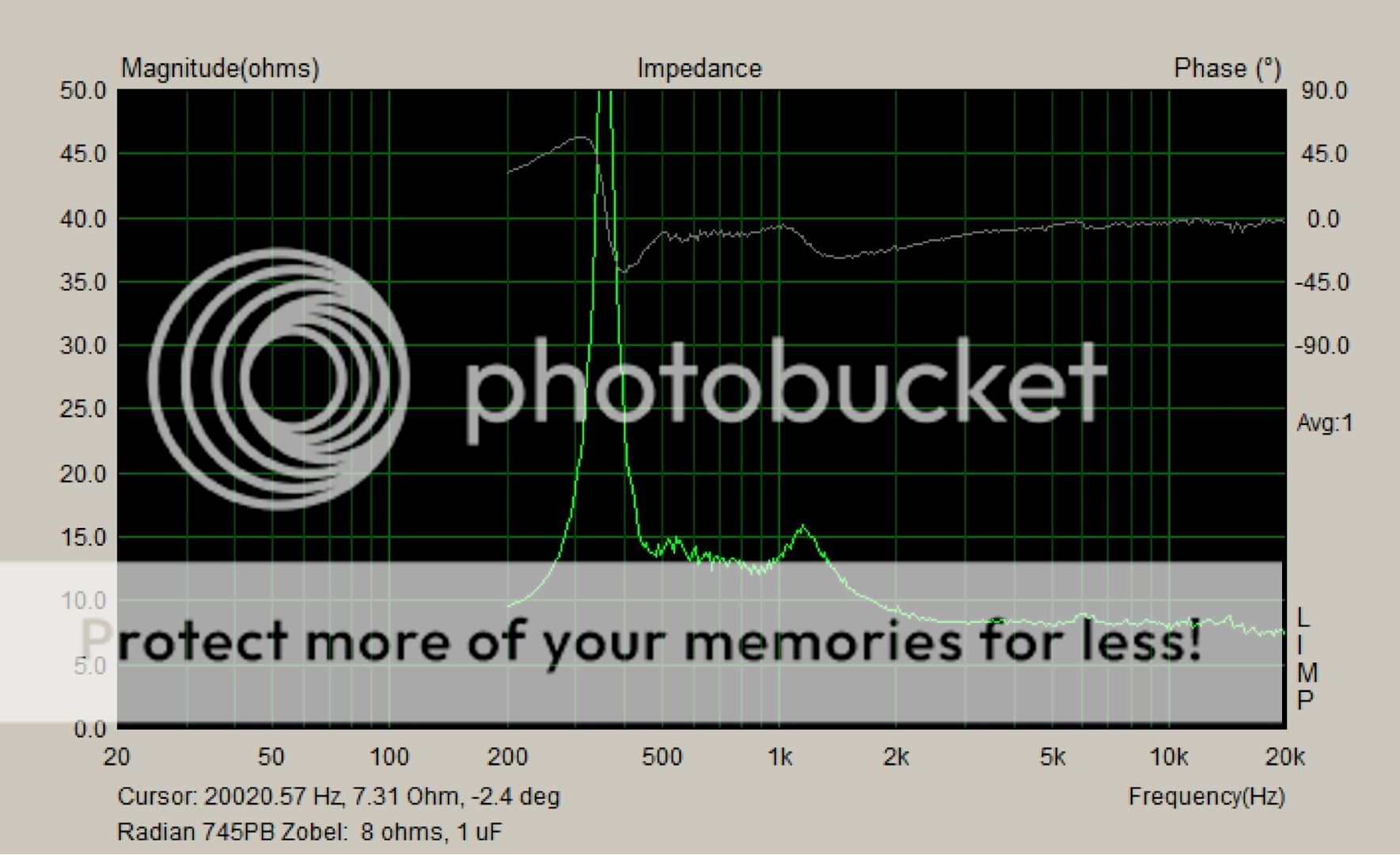
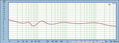
Decoupling back EMF or any kind of stored energy from the amp is always a good idea. This is also why I mention requirements for flat impedance. The more gradual the slopes in the impedance generally is an indicator of less energy stored in the circuit. Attached is an impedance example of (if I recall correctly) a two way MTM small speaker in ported enclosure(s) crossed at around 10KHz. Attempt was make to smooth out the impedance adding as little components as possible, even the two peaks normally exsiting in ported enclosures were no exception. Listening was conducted on a HAFLER XL-280 amplifier.
Very interesting that you mention the sensitivity of swapping speaker cables. I've recently been doing some measurements with interconnects also with similar findings. I'm gradually going through my lot of interconnects to figure out correlation.
Attachments
Last edited:
- Home
- Loudspeakers
- Multi-Way
- Beyond the Ariel