I'm honing on on a final design for an active loudspeaker. Each speaker will have built in amps and an on board MiniDSP 2x4 crossover. I'm interested in sending the signal to the speakers as digital info (to save the extra conversions from digital to analog and then back to digital if I used analog inputs). It seems that I need to get a pair of MiniDIGI boards and connect one to the 2x4 in each speaker. This leaves the problem of how to control the volume of the speaker pair simultaneously, because I assume that the digital signal will be at full level.
From what I can tell, my only option with the 2x4 is to use the on-board potentiometer volume control connections. I would set up one speaker as the "master" and the other(s) as slave(s). The master would supply the 3.3V control voltage and ground to the terminals of a potentiometer that is centrally located (e.g. back with the rest of the audio gear). The wiper voltage would then be returned to the speakers as volume control, perhaps with some filtering in the speaker to limit noise interference. This would work with additional speakers (e.g. for multi-channel audio).
Using the above scheme, I would need to construct a "control box" that has the volume potentiometer, a buffered splitter for the S/PDIF lines leading to each speaker, and digital inputs and perhaps switching for whatever source(s) I want to connect to the speakers. All this seems doable, but requires construction and the extra three wires to and from each speaker.
How about a digital preamp? For instance, let's say I am using a CD transport source - is there a solution that would upconvert, do a digital "volume control" and then output S/PDIF to the MiniDIGI at 24/96? I'm not too familiar with that area of audio... Remember, I need a separate buffered S/PDIF output (on coax or toslink) for EACH SPEAKER from the preamp, so I am not sure such a beast exists currently unless I also buy a dedicated splitter.
Any suggestions are welcome.
-Charlie
Charlie
I am standing over the same cooking pot for a while now and have to solve some issues myself.
Before proceeding further, I would like to ask you some questions.
1. Are you going for a stereo or multichannel system?
2. Assuming a stereo system, how many ways are your L & R speakers?
3. Have you decided on the power amplifier modules? What input signal do they accept (Analogue or I2S digital) ?
George
Last edited:
Charlie
I am standing over the same cooking pot for a while now and have to solve some issues myself.
Before proceeding further, I would like to ask you some questions.
1. Are you going for a stereo or multichannel system?
2. Assuming a stereo system, how many ways are your L & R speakers?
3. Have you decided on the power amplifier modules? What input signal do they accept (Analogue or I2S digital) ?
George
Hi George,
Here's a little more detail:
Loudspeakers are 4-way, stereo. The amplifiers require analog input. I would like to send the digital signal to the onboard MiniDSP crossovers. These are the 2x4, so I need to use the MiniDIGI to convert the S/PDIF to I2S which is then routed to the 2x4. The 2x4 interface allows you to select the digital I2S input stream instead of the analog one. This will save an extra conversion from digital to analog and back again, which should preserve fidelity as much as possible.
I will also need to control the volume somehow. It seems that the more straightforward way is to use the onboard volume control connections (as outlined in the 2x4 manual), but I would like to control the volume from where the rest of the stereo components are located. To do this I would run a 3-conductor cable from each speaker to a "volume control" unit that I would build. One speaker supplies the DC 3.3V source, which is varied in the volume control using a linear pot. The wiper output is returned to the 2x4 volume control pins in both speakers, so that they are controlled simultaneously. At this point it looks like this is the approach that I will use.
I am concerned about the possibility of forming a nice loop antenna with the wires running to and from the 2x4 board on each speaker. There is no ground connection at the volume control unit, so I shouldn't be able to form a ground loop. I guess as long as the wires are run as a twisted pair/triple back and forth the antenna effect will also be negligible, but I could add on a simple low-pass passive filter before each 2x4 to reject noise.
-Charlie
Last edited:
There is no ground connection at the volume control unit, so I shouldn't be able to form a ground loop. I guess as long as the wires are run as a twisted pair/triple back and forth the antenna effect will also be negligible, but I could add on a simple low-pass passive filter before each 2x4 to reject noise.
-Charlie
Charlie
The third wire is ground.
Tomorrow I will run for you the potentiometer on my miniDSP via a 3meter cable to see of any interference cropping in.
George
Charlie
The third wire is ground.
Tomorrow I will run for you the potentiometer on my miniDSP via a 3meter cable to see of any interference cropping in.
George
Great! Let me know what you find out. I appreciate your test of the idea...
-Charlie
Charlie, if you use a stereo pot you can control two miniDSP boards without needing the master/slave arrangement. You can even get 4 and 6-gang pots for a multichannel system.
The user manual for the 2x4 says use a 10k linear pot, while the manual for the 2x8 says use a 10k or 100k log pot. I think the two systems work the same way, using the incoming signal (0 to 3.3v) to control the voltage produced by the DAC stage. Most likely the manual for the 2x8 is better info and the taper should be log, typical for a volume knob. The best pot would probably be a 100k log.
The user manual for the 2x4 says use a 10k linear pot, while the manual for the 2x8 says use a 10k or 100k log pot. I think the two systems work the same way, using the incoming signal (0 to 3.3v) to control the voltage produced by the DAC stage. Most likely the manual for the 2x8 is better info and the taper should be log, typical for a volume knob. The best pot would probably be a 100k log.
Charlie, sorry for the delay in responding.
Today I probed the output of the miniDSP for noise while working with the volume’s potentiometer wiring.
Analogue input was loaded with 1kOhm on the RCA connector and no input signal. Output was loaded with 10kOhm on the RCA connector. I was probing this analogue output with the oscilloscope probe. Intentionally I was measuring broadband (no LP filtering). Results as follows:
With miniDSP volume function disabled and without volume pot wiring connected: Output noise 15mVpp
With miniDSP volume function disabled and with 10cm free wiring but no volume pot: Output noise 15mVpp
With miniDSP volume function enabled and with 10k volume pot connected through 10cm twisted wires: Output noise 17mVpp with any pot setting.
With miniDSP volume function enabled and with 10k volume pot connected through 4.5m flat ribbon : Output noise 17mVpp with any pot setting.
With miniDSP volume function enabled and with 10k volume pot connected through 4.5m two+shield microphone cable : Output noise 17mVpp with any pot setting.
In a few words, the volume connection does not degrade the noise on the analogue out of miniDSP.
The auxiliary ADCs controlling the volume are 8bit having a step size of 12mV sampled at 48kHz. The max noise (HF, above 1MHz) I measured on the volume pin is 7mVpp, so no problem there too. (The Aux ADC inputs may have been also LP filtered through software)
These all are good news.
The gray area is that I haven’t measured (I don’t know how to do it) what happens with the timing circuits and the PLL, as some of them are powered by the 3.3Vdc.
The operation of these circuits may be disturbed by the extra cabling. If this can be confirmed by others, a local LDR controlled by a LED may be a proper "remote" volume solution there.
The bad news is the amplitude of the noise at the analog out. 15mVpp(~5mVrms) is only 44 to 45db down rel to the max output of 900mV rms (I have measured max undistorted 850mVrms).
This 15mVpp noise is broadband as I said. Most of it’s content is above 1MHz.
I don’t know if it would be technically correct to LP filter first and then express a proper S/N ratio, but for sure this noise has to be adequately LP filtered at the analog input of the downstream power amplifier.
George
Last edited:
George,
Thanks for reporting all your findings! Great work. It looks like the volume control will work fine.
I'm a little skeptical of your noise readings... what power supply are you using?
I've seen measurements of the S/N reported elsewhere and the result was much better. For instance:
http://www.diyaudio.com/forums/minidsp/175810-any-measurements-minidsp.html#post2340627
Also, the manufacturer lists the noise level as -95dB.
-Charlie
You are welcome
I have pointed out that measurement was broadband and the noise is high on the spectrum.
MiniDSP states dynamic range as >98 db unweighted but they should have specified the frequency band of the measurement too. This, couldn’t go beyond 24kHz
Analoge Devices specifies for the ADAU1701 DAC out, signal to noise ratio as 104db and dynamic range as 104db but both A-weighted. (*)
http://www.analog.com/static/imported-files/data_sheets/ADAU1701.pdf
All digital equipment are measured over a limited HF frequency range, otherwise specs numbers would be embarrassing.
The reason I reported broadband measurement was to show that there is a reason to LP filter the analog out before it enter the power amplifier active stages.
Measurements on the link you provided are up to ~ 20kHz and they don’t lie.
You made a good point on the PSU. It affects the operation characteristics a lot. I am working on it (measurements).
The measurements I have posted were done with a hefty stabilized bench PSU.
Voltage was 12Vdc, noise is 1.5mVpp broadband (most above 1MHz) when loaded with anything above 100Ohm.
I have also to report the broadband noise pick-up of the oscilloscope probe loaded with 10kOhm.
0.2mVpp with miniDSP off, 0.8mVpp with miniDSP on
George
(*) To get an idea of the A-weighting effect on HF noise measurement, see the attenuation imposed by this weighting (i.e. data filtering)
7kHz –0.5db
10kHz –2.5db
20kHz –9.3db
30kHz –15db
50kHz –23db
100kHz –34.7db
500kHz –62.5db
1MHz –74.5db
2MHz –86.6db
3MHz –93.6db
5MHz –102db
10MHz –114.5db
Last edited:
Hi George,
Thanks for clarifying. I see your point:
Since you are familiar with the measurements you made, what would you suggest for a filter (order and corner frequency). Would something like a single pole LP at 50kHz provide sufficient attenuation?
-Charlie
Thanks for clarifying. I see your point:
I think that you have sent a strong message! I never thought that there would significant above band (e.g. above 20kHz) noise from the DSP unit, and yes this can do some bad things in the power amp if it isn't filtered out.The reason I reported broadband measurement was to show that there is a reason to LP filter the analog out before it enter the power amplifier active stages.
Since you are familiar with the measurements you made, what would you suggest for a filter (order and corner frequency). Would something like a single pole LP at 50kHz provide sufficient attenuation?
-Charlie
Charlie
Every digital circuit generates HF EM fields. These can couple to everything in the vincinity, on board and to it’s connections to the other circuits.
E.g. The clean psu I wrote above, when probed while feeding the working miniDSP shows a nasty waveform 100mVpp whose lowest frequency is at ~1MHz -despite psu very low internal impedance- thanks to the 50cm connecting twisted leads. Local decoupling and filtering at the board’s dc entry then is a must, particularly when one psu is feeding other boards too. Same effects and treatment is to be thought of for all connections, these for analogue signals too.
This is not a problem with only this DSP unit. You can open the cover of a CD unit or a digital radio and probe around.
To your question: The single pole 30-50kHz LP filter at amp input, will reduce the 15mVpp 1MHz noise into around a 0.5mVpp one (-30db), much lower for the higher harmonics. Not bad at all.
A two pole filter will reduce this noise to a theoretical 10uV (-64db).
George
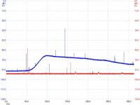
Here's a noise measurement (from a few years ago) showing miniDSP 2x4 (red) versus 2x8 (blue) output noise. This plot spans a 300khz bandwidth, but I also checked to 5Mhz. The output noise of the 2x4 unit does not rise above -91dbV in the 5Mhz range.
I don't see any issue with low-pass filtering the outputs, but there isn't much to filter...with the 2x4 unit.")
Cheers,
Dave.
I don't see any issue with low-pass filtering the outputs, but there isn't much to filter...with the 2x4 unit.
Cheers,
Dave.
Attachments
Fellas,
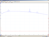
Here's a better look with a measurement I just made.
This is my miniDSP 2x4 with all processing disabled, all gains set to 0db, and input shorted. (blue trace.)
The red trace is the other channel of my (el-cheapo) USB spectrum analyzer with a shorted input.....for reference.
The analyzer auto-scaled to its lowest input range to yield this measurement. The miniDSP noise is highest in the 1.5Mhz range but only approximately -88dbV worst case.
The miniDSP 2x8 is a different animal with completely different noise characteristics.
Cheers,
Dave.
Attachments
Dave thank you for the new plot.
I looked at my other miniDSP board. Output noise is of the same amplitude as previously reported with a bit higher frequency components.
The huge difference compared to your measurements makes me wonder what is going on. It is not a ground loop issue, it is not a psu issue. I tested any feasible combination of these two.
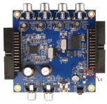
Using my 10mm x 10mm one-turn H-Field probe, I looked around the board and I spoted the troublemaker. It is the L1 (56uH) coil.
What this probe sensed close to L1 coil is a square signal 0.52 us repeating every 0.74us with an amplitude of 30mV. This spreads out frequencies of 1.92Mz, 1.35MHz and 50MHz (the steep edges having a rise and fall rate of 24mV/0.008us).
Probing the DC input which is very close to L1, I saw a strong 48mVpp footpring of this squarewave with less steep edges and well damped 50MHz ringing.
On the 3.3Vdc probed at pins 34, 36, 48 of ADAU1701 the squarewave ghost is 8mVpp and the 50MHz ringing is 3mVpp.
On the 1.8Vdc probed at pins 13, 24 of ADAU the squarewave is 16mVpp and the 50MHz ringing is 12mVpp. (*)
All these with 12Vdc supply voltage. L1 field strength and the amplitude of the coupled square wave pattern increase with voltage, becoming almost double with supply voltage of 24Vdc (the 50MHz coupled wavetrain retains the same amplitude being the result of rise time which doesn’t change with voltage).
When I was moving the H-field probe around L1, the current consumption of the board was fluctuating due to the stray coupling of the probe with the magnetic field. This means that a screen around L1 will affect it’s (unknown to me) operation.
I’ll try to repair the dead board and use it for working around L1.
Meanwhile, is it possible for some of you to probe with a scope the analog out of a 2x4 miniDSP (no signal on input) and report here?
George
(*) The amplitude of noise at 3.3V and 1.8 V pins change with the position of probe’s ground (this is how I fried the other board. The ground wire slipped...)
I looked at my other miniDSP board. Output noise is of the same amplitude as previously reported with a bit higher frequency components.
The huge difference compared to your measurements makes me wonder what is going on. It is not a ground loop issue, it is not a psu issue. I tested any feasible combination of these two.
Using my 10mm x 10mm one-turn H-Field probe, I looked around the board and I spoted the troublemaker. It is the L1 (56uH) coil.
What this probe sensed close to L1 coil is a square signal 0.52 us repeating every 0.74us with an amplitude of 30mV. This spreads out frequencies of 1.92Mz, 1.35MHz and 50MHz (the steep edges having a rise and fall rate of 24mV/0.008us).
Probing the DC input which is very close to L1, I saw a strong 48mVpp footpring of this squarewave with less steep edges and well damped 50MHz ringing.
On the 3.3Vdc probed at pins 34, 36, 48 of ADAU1701 the squarewave ghost is 8mVpp and the 50MHz ringing is 3mVpp.
On the 1.8Vdc probed at pins 13, 24 of ADAU the squarewave is 16mVpp and the 50MHz ringing is 12mVpp. (*)
All these with 12Vdc supply voltage. L1 field strength and the amplitude of the coupled square wave pattern increase with voltage, becoming almost double with supply voltage of 24Vdc (the 50MHz coupled wavetrain retains the same amplitude being the result of rise time which doesn’t change with voltage).
When I was moving the H-field probe around L1, the current consumption of the board was fluctuating due to the stray coupling of the probe with the magnetic field. This means that a screen around L1 will affect it’s (unknown to me) operation.
I’ll try to repair the dead board and use it for working around L1.
Meanwhile, is it possible for some of you to probe with a scope the analog out of a 2x4 miniDSP (no signal on input) and report here?
George
(*) The amplitude of noise at 3.3V and 1.8 V pins change with the position of probe’s ground (this is how I fried the other board. The ground wire slipped...)
Attachments
Last edited:
[snip]This is my miniDSP 2x4 [snip]
Dave, which 2x4 board were you testing (unbalanced or balanced) and was it a bare board in the open, something you assembled (with PS, in an enclosure), or was it the 2x4-in-a-box with a wall wart PS?
-Charlie
I bet a couple of beers that L1 is part of a voltage step down (“buckle”) circuit. All the necessary elements are around, it’s location on the board and the increase of the magnetic field with the increase of the applied dc, all hint to that. I’ll check it in a couple of hours.
George
George
Attachments
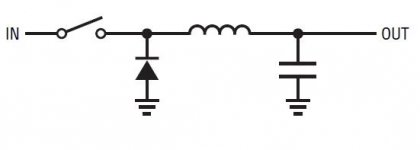
The above is verified. But where is the switcher?
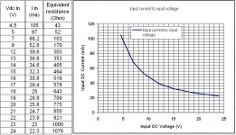
As a by-product, here is the current demand of the miniDSP v1.8 board in relation to the external psu DC voltage. This is the current after the momentary turn-on peak. This peak is ~ 3x higher.
George
As a by-product, here is the current demand of the miniDSP v1.8 board in relation to the external psu DC voltage. This is the current after the momentary turn-on peak. This peak is ~ 3x higher.
George
Attachments
- Status
- This old topic is closed. If you want to reopen this topic, contact a moderator using the "Report Post" button.