I am a physicist, but I know no such thing. As far as I recall, dielectric hysteresis and anisotropy are two quite distinct phenomena. You can have either without the other. One makes the material properties a function of field strength history; the other makes the material properties a function of direction.popilin said:As a physicist, you MUST KNOW that hysteresis is a consequence of anisotropy.
The scalar versions of the constitutive relationships are isotropic, but may be non-linear if permittivity is a function of field strength. On the other hand, the tensor version allows for anisotropy but will be linear if the elements in the tensor are all constants.
I don't understand your point about the disadvantages of large value capacitors. As Merlin says, large value means small voltage so small distortion. Very few people on here regard caps as ideal; if anything the problem is that they regard them as too non-ideal and hence waste money on expensive caps when ordinary well-chosen ones would be better.
I'll be honest, I haven't yet looked at the minutiae of harmonic cancellation in the SRPP myself, but it's something I intend to do at some point.Merlin, wrt my spontanous outburst of creativity, does the top resistor affect 2H?
Did I remember right that SRPP cancels distortion from equal but opposite AC conditions for both triodes?
On a coupling cap with enough DC bias, the dielectric is already polarized, so the electric field E doesn't changes its sign and consequently doesn't changes its sense of direction, this means no zero crossing.
Let's suppose now that we use a normal capacitor, and following the advice that it is said out there, we decide to replace it by an enormous capacitor, and being generous let's suppose also that both capacitors has same losses, i.e. same area inside the hysteresis loop.
Armchair theorizing is all very well, but your claims simply do not stand up again the real world evidence, which conclusively shows that the bigger the capacitor, the lower distortion. Take a 100nF polystyrene capacitor and put it up against a 10000uF electrolytic, and you won't be able to measure the distortion either way.
And how do you explain the fact that electrolytic capacitors exhibit their lowest distortion with a small bias voltage (a couple of volts) but worse distortion with large bias voltages, even if that means they never get reverse biased? It sounds to me like you've been reading too much, and measuring too little.
Yes, and like you he is guilty of sometimes spending a little too long theorizing and not enough time measuring. We're into the 4th edition and he still saying this about bipolar electrolytics: "Defects are thereby multiplied by a factor of four over the normal unipolar electrolytic capacitor, so their performance is poor." Which is simply not true. Their ESR is hardly any worse, and their distortion is an order of magnitude better than unipolars!Morgan Jones on his book "Valve Amplifiers" has an entire chapter about capacitors.
 But Jones hardly seems to mention capacitor distortion . He seems more preoccupied with leakage current and "imaginary capacitance" for heaven's sake!
 No he doesn't.Ah, by the way, he also encourage that don't using capacitors too big.
Last edited:
I am a physicist, but I know no such thing. As far as I recall, dielectric hysteresis and anisotropy are two quite distinct phenomena. You can have either without the other. One makes the material properties a function of field strength history; the other makes the material properties a function of direction.
A dielectric is composed by molecular dipoles randomly oriented, that's why it's anisotropic.
In response to an applied electric field E, the dielectric is polarized in a specific direction, if you remove the electric field E, the response of the medium is not instantaneous, molecular dipoles needs a time to get back to its initial state, it is called dielectric relaxation, and is the reason for dielectric hysteresis.
This also represents an increase of dielectric anisotropy, because under dynamic conditions, i.e. with applied electric field, dielectrics are even more anisotropic.
Then, dielectric anisotropy is analogous to magnetic anisotropy, even more, for very high permittivities, e.g. ceramic capacitors, dielectric hysteresis curve is quite similar in shape to magnetic hysteresis curve for ferromagnetic materials.
Maybe you could illuminate us with an example of a dielectric that exhibits hysteresis without anisotropy, i.e. hysteresis in a linear medium.
The scalar versions of the constitutive relationships are isotropic, but may be non-linear if permittivity is a function of field strength.
Well, it is not very original, but this traditional approach
D = ε(E) E
Would solve the non-linearity issue, but D cannot be a single-valued function of E, but this is a minor detail because mathematicians abound.
On the other hand, the tensor version allows for anisotropy but will be linear if the elements in the tensor are all constants.
Does not make sense to describe the permittivity of a linear medium with a tensor, with a scalar is enough, and a lot easier.
I don't understand your point about the disadvantages of large value capacitors.
I know that you are an ultrafast reader, but warn you that my Tarzan-English is a big challenge, if you read more carefully my posts, you will see that I have nothing against big capacitances, the problem is, with a reasonably good dielectric, that implies big sizes, big volumes, and this increases losses, and losses deteriorates linearity, so beyond certain limit you will cancel/ruin the desired effect.
Very few people on here regard caps as ideal; if anything the problem is that they regard them as too non-ideal and hence waste money on expensive caps when ordinary well-chosen ones would be better.
Totally agree, I myself strongly disagree with audio foolish capacitors, and I consider more than reasonable standard industrial grade MKPs, for most valve amplifiers and preamplifiers.
Sadly, with the line of thought "bigger is better" very soon we will see chassis with capacitors bigger than transformers...
Armchair theorizing is all very well, but your claims simply do not stand up again the real world evidence, which conclusively shows that the bigger the capacitor, the lower distortion.
Seems to me that you didn't get it, so I will repeat in a more crude
The bigger the capacitance, the lower distortion.
The bigger the capacitor/size/volume/dimentions => the bigger losses => the lower linearity.
Take a 100nF polystyrene capacitor and put it up against a 10000uF electrolytic, and you won't be able to measure the distortion either way.
Let's advise people that they must use 10000 μF electrolytics.
I pass, thanks.
And how do you explain the fact that electrolytic capacitors exhibit their lowest distortion with a small bias voltage (a couple of volts) but worse distortion with large bias voltages, even if that means they never get reverse biased?
For the record, this time you said it, not me.
Casually, electrolytic capacitors are leaky, and leakage current is increased with applied voltage, so again
the bigger losses => the lower linearity.
It sounds to me like you've been reading too much, and measuring too little.
It sounds to me like you've been measuring too much, and reading too little, including my posts.
The Elliot web page is good and for me useful.
Perhaps for you gentlemen, more physic a la Sears-Semansky is adequate.
But anybody is free to choice which thread read in the early morning without enough coffe.
Maybe for my rudimentary dimension is to much further but I think I will read Elliot's page.
Perhaps for you gentlemen, more physic a la Sears-Semansky is adequate.
But anybody is free to choice which thread read in the early morning without enough coffe.
Maybe for my rudimentary dimension is to much further but I think I will read Elliot's page.
The bigger the capacitance, the lower distortion.
The bigger the capacitor/size/volume/dimentions => the bigger losses => the lower linearity.
Casually, electrolytic capacitors are leaky, and leakage current is increased with applied voltage, so again
the bigger losses => the lower linearity.
Where's the power rating in this story? The formation of aluminium oxide takes time and power. When caps are used at the limit of their working voltage they won't behave very linear either.
If I'm correct you're saying purists have to exchange their oil drums for miniature foils for the better. That thought won't be received with open arms

It sounds to me like you've been measuring too much, and reading too little, including my posts.
And yet, measurement and experiment are the final answer. Do you have any actual experimental data to show that your assertion here is correct?
No, the opposite is true. Random orientation guarantees isotropy! It is when dipoles are not random that you can get anisotropy.popilin said:A dielectric is composed by molecular dipoles randomly oriented, that's why it's anisotropic.
I fear you may have misunderstood the meaning of dielectric anisotropy.This also represents an increase of dielectric anisotropy, because under dynamic conditions, i.e. with applied electric field, dielectrics are even more anisotropic.
You appear to be confusing linearity with isotropy.Maybe you could illuminate us with an example of a dielectric that exhibits hysteresis without anisotropy, i.e. hysteresis in a linear medium.
No. A linear anisotropic medium would need a tensor. You persist in confusing the effects of direction with the effects of field strength. A non-linear isotropic medium does not need a tensor.Does not make sense to describe the permittivity of a linear medium with a tensor, with a scalar is enough, and a lot easier.
You need to understand a bit more basic physics before you pontificate about capacitor size etc.
And yet, measurement and experiment are the final answer. Do you have any actual experimental data to show that your assertion here is correct?
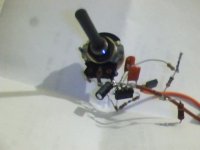
I'm sorry, no, I'm poor and my instruments are a couple of old multimeters, an old 15 MHz oscilloscope, but a superduper signal generator.
However, this thread was speculative from the beginning, if the lack of measurements is an issue, I apologize.
Fortunately, Merlinb did his own contribution to support my point.
BTW, the quality of my solders is due to low resolution of the photo.
Attachments
No, the opposite is true. Random orientation guarantees isotropy! It is when dipoles are not random that you can get anisotropy.
Without dielectric anisotropy, the dipoles randomly change direction in response to thermal fluctuations, but you forget a little detail, we are talking about capacitor dielectrics and they are ferroelectric in some degree, so forget isotropy !
Mind you that today, most electrets are made from synthetic polymers, e.g. fluoropolymers like PTFE (AKA Teflon), polypropylene, polyethylene terephthalate, polyester, polystyrene, etc.
I fear you may have misunderstood the meaning of dielectric anisotropy.
No, you do, let me explain
As I said before, with an applied external electric field E, the dielectric is even more anisotropic, because electric dipoles clearly have a privileged orientation, even after the external electric field E was removed.
You can verify this experimentally, just charge a capacitor with a battery, remove the battery, you can see for yourself that the capacitor remains charged from minutes to years, depending on how ferroelectric is its dielectric.
How would you call this? Dielectric anisotropy or dielectric hysteresis?
You appear to be confusing linearity with isotropy.
I'm sorry, asking homogeneity in addition to isotropy maybe it is too much, so I will reformulate my request
Maybe you could illuminate us with an example of a dielectric that exhibits hysteresis without anisotropy.
No. A linear anisotropic medium would need a tensor.
In an anisotropic medium, constitutive relations are
Di = εij(ω) Ej
Bi = μij(ω) Hj
Bi = μij(ω) Hj
Where
εij(ω) is the permittivity tensor
μij(ω) is the permeability tensor
If all elements of the tensor are constant, an anisotropic medium can have a linear response, sadly has been lost the time/frequency dependence, and your proposal of post#201 is useless, except for the electrostatic case, nice try though.
You persist in confusing the effects of direction with the effects of field strength.
No, you are denying from the beginning that hysteresis is a consequence of anisotropy.
In ferromagnetic materials, the relation between B and H exhibits both nonlinearity and hysteresis, B is not a single valued function of H, magnetic anisotropy is a prerequisite for hysteresis in ferromagnetic materials.
Analogously, in capacitor dielectrics, the relation between D and E exhibits both nonlinearity and hysteresis, D is not a single valued function of E, dielectric anisotropy is a prerequisite for hysteresis in capacitor dielectrics.
You need to understand a bit more basic physics before you pontificate about capacitor size etc.
Seems to me this is a bit premature, answer my request before sending me to study.
Last edited:
we are talking about capacitor dielectrics and they are ferroelectric in some degree...
you can see for yourself that the capacitor remains charged from minutes to years, depending on how ferroelectric is its dielectric.
How would you call this?
I would call this a non-understanding of electrical properties of polymers and ferroelectricity.
Any amorphous polymer containing polar groups will be isotropic (by definition) yet show hysteresis to a greater or lesser degree.
Any amorphous polymer containing polar groups will be isotropic (by definition)
So you mean that electrets are isotropic too?
yet show hysteresis to a greater or lesser degree.
Can you please explain to me how?
Are they? Not all materials used as capacitor dielectrics are ferroelectric.popilin said:we are talking about capacitor dielectrics and they are ferroelectric in some degree
Yes, I am. I am glad you are listening. Show me a textbook which says that hysteresis is a consequence of anisotropy, so that the two effects always occur together.No, you are denying from the beginning that hysteresis is a consequence of anisotropy.
Listen to what SY says. He is an expert on this sort of stuff. Throw away your false assumptions/misunderstandings and start again. You may end up with an understanding of dielectrics!
So you mean that electrets are isotropic too?
No. But in order to form an electret, the material has to be taken above its glass transition, a very strong field applied, and the the temperature lowered without removing the field until it's (essentially) quenched. That's irrelevant to capacitor films.
As far as I recall, dielectric hysteresis and anisotropy are two quite distinct phenomena. You can have either without the other.
Maybe you could illuminate us with an example of a dielectric that exhibits hysteresis without anisotropy.
yet show hysteresis to a greater or lesser degree.
Can you please explain to me how?
Nobody answered.
I however, must justify everything I say, and even demanding to me measurements.
Seems that I must do my own research.
Meanwhile, late at night, I found on the web
1) Linear Polyethylene (PE), Polyethylene terephthalate (PET), Polytetrafluoroethylene (PTFE), Isotactic Polypropylene (PP).
Are not amorphous polymer, but semi-crystalline polymers.
2) Polystyrene is an amorphous polymer.
3) Semi-crystalline polymers has both behavior in some degree, i.e. as amorphous polymers and as crystalline polymers.
But the article was not very clear.
4) A Master thesis about anisotropy in semi-crystalline polymers.
5) Also exist ferroelectric polymers, such as polyvinylidene fluoride (PVDF)
6) Evidence of ferroelectric behavior of other types of polymers, such as odd nylons, VDCN copolymers, FLCP, PTFE, etc.
Maybe all those people have the same non-understanding of electrical properties of polymers and ferroelectricity as me, who knows.
Unfortunately I was almost asleep, and after switch off the pc I remembered that its hard disk is frozen, so today morning all information was gone, but don't care, I have no hurry.
Although dielectric hysteresis is smaller than magnetic hysteresis, analogies are so strong to ignore them.
Listen to what SY says. He is an expert on this sort of stuff.
Agree, he is THE expert, but also he seems to be a very good poker player, so let me be just a bit suspicious.
Throw away your false assumptions/misunderstandings and start again. You may end up with an understanding of dielectrics!
I thank you, but needless you say that, the goal of science is the truth about reality, not to win a discussion, if I realize that I'm wrong surely I will start again.
No. But in order to form an electret, the material has to be taken above its glass transition, a very strong field applied, and the the temperature lowered without removing the field until it's (essentially) quenched.
Not all electrets are produced this way, the electret state can occur in a dielectric even without the external field application, but, e.g. from mechanical deformation (mechanoelectrets); during dielectric charging in corona discharge (coronaelectrets); at polymer heating in contact with unlike metals (metal-polymer electrets); at friction-induced electrification (triboelectrets); with electron bombardment...
That's irrelevant to capacitor films.
There are lot of similarities with capacitors, but you are the specialist, so no more comments.
popilin said:Maybe you could illuminate us with an example of a dielectric that exhibits hysteresis without anisotropy.
SY said:Any amorphous polymer containing polar groups will be isotropic (by definition) yet show hysteresis to a greater or lesser degree.
I am not trying to 'win' a discussion; experience teaches me that is unlikely to happen. I am trying to correct errors put forth in a public forum, so others are not mislead.popilin said:I thank you, but needless you say that, the goal of science is the truth about reality, not to win a discussion, if I realize that I'm wrong surely I will start again.
Indudablemente
I think that there are enough information for learn, some body could appreciate the scientific interchange of information. You gentlemen, further this interchange, seems that not read or worse, misinterpret that the other say, nobody add some extra info, only refutations. For somebody occasional viewer looks like nobody know what is true or false. Nobody remit to bibliography, maybe you give for knew every formulae or graphic. I also understood that there are info for every body and maybe this is not for somebody else like most of the members. Please to you that could read the point of view of a profane man of the diyaudio world.
I think that there are enough information for learn, some body could appreciate the scientific interchange of information. You gentlemen, further this interchange, seems that not read or worse, misinterpret that the other say, nobody add some extra info, only refutations. For somebody occasional viewer looks like nobody know what is true or false. Nobody remit to bibliography, maybe you give for knew every formulae or graphic. I also understood that there are info for every body and maybe this is not for somebody else like most of the members. Please to you that could read the point of view of a profane man of the diyaudio world.
My dear friend, I will try to give my point of view.
While this is a technical forum, there is no court that previously verify the information, as in academic publications, as a result, anyone can say anything.
I feel a moral duty to have the intellectual honesty to justify all my statements and I sincerely believe that my ideas are not so crazy, but they are never well received.
As this is a public forum, I must accept it with humility and resignation.
This particular thread from the beginning was speculative, and in this context can be a little difficult to understand.
Not to be pedantic, but the results that I present are not always in the books, which makes almost impossible any bibliographic citation.
Beyond certain fine details, the idea that the linearity of capacitors is related to the area inside dielectric hysteresis loop is not new
The "Sound" of Capacitors
However, the work of Mr. Bench was also criticized, and accused of not seeing dielectric hysteresis but dielectric absorption
http://www.diyaudio.com/forums/tubes-valves/233663-cathode-bypass-capacitor-10.html#post3448897
For the record, dielectric absorption and dielectric hysteresis refer to the same phenomenon.
However, the effect of dielectric hysteresis is much less obvious than that of magnetic hysteresis, in terms of distortion I estimate about an order of magnitude lower, that's why it is difficult to measure.
Maybe my speculations only have theoretical value, but in practice, because of my limited budget, I only have a silver bullet, that's why I always use reasonable size capacitors.
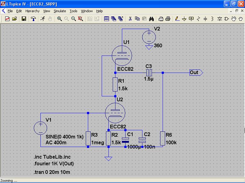
C1 = 1000 µF / 16 V Electrolytic
C2 = 100 nF / 63 V MKP
C3 = 1.5 µF / 400 V MKP
I assure you that it sounds amazingly transparent, I do not have measurements, and photos, you already has seen them.
I think that there are enough information for learn, some body could appreciate the scientific interchange of information. You gentlemen, further this interchange, seems that not read or worse, misinterpret that the other say, nobody add some extra info, only refutations.
While this is a technical forum, there is no court that previously verify the information, as in academic publications, as a result, anyone can say anything.
I feel a moral duty to have the intellectual honesty to justify all my statements and I sincerely believe that my ideas are not so crazy, but they are never well received.
As this is a public forum, I must accept it with humility and resignation.
For somebody occasional viewer looks like nobody know what is true or false. Nobody remit to bibliography, maybe you give for knew every formulae or graphic. I also understood that there are info for every body and maybe this is not for somebody else like most of the members. Please to you that could read the point of view of a profane man of the diyaudio world.
This particular thread from the beginning was speculative, and in this context can be a little difficult to understand.
Not to be pedantic, but the results that I present are not always in the books, which makes almost impossible any bibliographic citation.
Beyond certain fine details, the idea that the linearity of capacitors is related to the area inside dielectric hysteresis loop is not new
The "Sound" of Capacitors
However, the work of Mr. Bench was also criticized, and accused of not seeing dielectric hysteresis but dielectric absorption
http://www.diyaudio.com/forums/tubes-valves/233663-cathode-bypass-capacitor-10.html#post3448897
For the record, dielectric absorption and dielectric hysteresis refer to the same phenomenon.
However, the effect of dielectric hysteresis is much less obvious than that of magnetic hysteresis, in terms of distortion I estimate about an order of magnitude lower, that's why it is difficult to measure.
Maybe my speculations only have theoretical value, but in practice, because of my limited budget, I only have a silver bullet, that's why I always use reasonable size capacitors.
C1 = 1000 µF / 16 V Electrolytic
C2 = 100 nF / 63 V MKP
C3 = 1.5 µF / 400 V MKP
I assure you that it sounds amazingly transparent, I do not have measurements, and photos, you already has seen them.
Attachments
Last edited:
- Status
- This old topic is closed. If you want to reopen this topic, contact a moderator using the "Report Post" button.
- Home
- Member Areas
- The Lounge
- ECC82/12AU7 Line Preamp