I like the theory behind them. However, when I first examined them, code did not allow the use of any reactance in the safety bond, it was a total violation.
John
Okay Richard,
So my power drop into the house is on one side of the house and the CATV box is on the opposite side, now what do you do? How do you now after the fact correct this situation and break a ground loop?
Well, I have to back up then...... I measured my earth ground near the power entrance panel's ground. I thought I could make a better ground bond. 9-12 foot copper clad steel rod... earth prepped with copper sulfate solution.
You will need one of these to make a good earth ground and to know the results (before and after and during):


There were 3 ways tried. I laid down a 12 awg wire attached at the CATV ground and ran it 100 feet to the ac power ground. This dropped the resistance and voltage drop. If you can trench and fill wth large gauge cable around the house and connect the two.... this is effective.
You can also make a small box with smd cap in series with the ground side of the CATV cable. This will break the 60Hz path or use a 1:1 wide bandwidth 75-75 Ohm isolation transformer (good to >1GHz). Or a 3rd way which is propriatory for now.
For most people here at DIY-land a small series cap in the ground lead of the CATV coax works very well. I think 0.01mfd was tried.
THx-RNMarsh
Last edited:
JN,
So in m older house not using Romex type wiring I have a 208v or 220v line entering the house, two legs of 110v power and a neutral is how I understand it. So the neutral is the ground leg of the system and then the switch panel/ breaker box is connected to ground with a ground spike. The entire house has metal conduit, so that also is connected back to the panel by direct connection and that is also grounded through the ground spike by the ground strap connection to the panel. Can't say how many grounds are along the power line coming to the house as the utilities are underground where I live. Now the CATV box is on the other side of the house and is also grounded to a ground spike and a ground strap to the incoming box. Am I only worrying about lightening or am I also looking for a ground loop between the ground spikes on opposite sides of the house, what are my concerns with this type of connectivity and my audio system? Do I just connect all of my audio system to a single strip type power outlet and consider that a small ground loop potential? So everything running off of one power outlet and one power strip?
So in m older house not using Romex type wiring I have a 208v or 220v line entering the house, two legs of 110v power and a neutral is how I understand it. So the neutral is the ground leg of the system and then the switch panel/ breaker box is connected to ground with a ground spike. The entire house has metal conduit, so that also is connected back to the panel by direct connection and that is also grounded through the ground spike by the ground strap connection to the panel. Can't say how many grounds are along the power line coming to the house as the utilities are underground where I live. Now the CATV box is on the other side of the house and is also grounded to a ground spike and a ground strap to the incoming box. Am I only worrying about lightening or am I also looking for a ground loop between the ground spikes on opposite sides of the house, what are my concerns with this type of connectivity and my audio system? Do I just connect all of my audio system to a single strip type power outlet and consider that a small ground loop potential? So everything running off of one power outlet and one power strip?
Last edited:
Typing at the same time Richard. So how does that capacitor on the ground line go, just in series and is that legal? What would happen to that cap if there was a lightning strike? Luckily for me I live with a large Antenna tower above my house, any lightning is hitting that 100 foot tower if it is hitting anything!
I like the theory behind them. However, when I first examined them, code did not allow the use of any reactance in the safety bond, it was a total violation.
John
I've heard back and forth on the subject. Schurter says they saturate when passing anything, and turn into a 12ga wire. They claim there's numerous UL/CE passed products using them.
But I can also note there's often confusion between what's acceptbale externally (part of building) and internally with appliances. I've read a lot of stuff that isn't applicable. Some people even ask where's the UL approval but UL only approves stand alone devices such as AC receptacles and entire appliances, not parts.
The only thing to do is send something in for UL approval using one, for one to be certain, personally, beyond a shadow of a doubt.
JN,
So in m older house not using Romex type wiring I have a 208v or 220v line entering the house, two legs of 110v power and a neutral is how I understand it. So the neutral is the ground leg of the system and then the switch panel/ breaker box is connected to ground with a ground spike. The entire house has metal conduit, so that also is connected back to the panel by direct connection and that is also grounded through the ground spike by the ground strap connection to the panel. Can't say how many grounds are along the power line coming to the house as the utilities are underground where I live. Now the CATV box is on the other side of the house and is also grounded to a ground spike and a ground strap to the incoming box. Am I only worrying about lightening or am I also looking for a ground loop between the ground spikes on opposite sides of the house, what are my concerns with this type of connectivity and my audio system? Do I just connect all of my audio system to a single strip type power outlet and consider that a small ground loop potential? So everything running off of one power outlet and one power strip?
Having the cable on the other side of the house is called an "upside down house". Martzloff wrote about that.
http://www.lightningsafety.com/nlsi_lhm/surge-protection.pdf
Page 5 on the right looks like the house you describe.
If I were you, I'd use a multiport SPD at the point of use just to be sure. A strike at the antennae tower could create voltages in wire loops that could damage inputs, especially the cable box to tv.
I lost a DVD player and a smoke detector at the same time when a tree about 100 feet away was hit. The cable feeding the dvd climbed to the second floor on the wall opposite the power feeds. The smoke detector also had a large loop.
John
Last edited:
JN,
Yes originally the CATV drop was on the same side as the power panel but later they upgraded their system and went to the least distance from their underground utility box and put the cable connection on the other side of the house. So I think it was a legal connection when the house was built and now it is the same as that house on page 5. Figures they would ignore code, Time Warner cable.
I guess the question is should I lift the ground on the CATV and run a wire to the other side of the house and connect to the original connection, the water pipe and spike at the ac panel? What gauge wire would be necessary to go about 75 feet and still have good grounding potential?
Last edited:
JN,
Yes originally the CATV drop was on the same side as the power panel but later they upgraded their system and went to the least distance from their underground utility box and put the cable connection on the other side of the house. So I think it was a legal connection when the house was built and now it is the same as that house on page 5. Figures they would ignore code, Time Warner cable.
I guess the question is should I lift the ground on the CATV and run a wire to the other side of the house and connect to the original connection, the water pipe and spike at the ac panel? What gauge wire would be necessary to go about 75 feet and still have good grounding potential?
Do not break the ground where the catv attaches to the house. The ground there serves two very important functions.
1. Provides a direct path for a lightning strike to the earth so that the bolt does not attempt to reach earth through the cable feeding into your house.
2. Provides that oh so endearing HUM for audiophiles.
NEC is not designed to eliminate hum for us, only to try to keep us a bit safer.
If you have hum, I would consider a ground isolation transformer for the CATV, I believe richard mentioned that.
Otherwise, just use a multiport SPD at the box.
John
Thanks JN. I guess we could say it is off topic but really has direct connection to audio quality. I'm going to look at how the original connections were made and see if I can recreate the original connections. Got to figure out how the original drop was done and perhaps move the incoming box back to the other side of the house.
Mostly we are talking about safety earthing etc. Lightning protection is smaller issue here -- a rare problem.
We have PME - no real earths, though I have a massive earth grid out the back under a small field.. Used for TX antennas for measurements over ground plane where required for the day job.
Not hooked any audio gear to it though, as yet...")
Hum is definitely audible, but I don't recall the last time I heard or measured any relevant 50Hz or harmonic thereof on an audio system...
We have PME - no real earths, though I have a massive earth grid out the back under a small field.. Used for TX antennas for measurements over ground plane where required for the day job.
Not hooked any audio gear to it though, as yet...
Hum is definitely audible, but I don't recall the last time I heard or measured any relevant 50Hz or harmonic thereof on an audio system...
If for example, your tv power romex comes up one side of the house, and your cable comes up the other, you are ripe for disaster, it'll frost your inputs if a nearby strike happens.
I can attest to this. Back at our old house in ohio, cable came in one side, power and phone in the other side, water somewhere in the middle. In summer there was a big lightning strike into the back yard (blew about a 8" hole in the ground into a buried cable!), and lost a bunch of computers and phone stuff. There was an old Hafler DH200 amp that had it's 5W ground lift resistor (connected between input signal ground and chassis) literally explode. The amazing thing with that is that after I replaced the resistor, the amp worked normally again!
Leakage current can take its way along grounded Antenna wirings, for instance.Luckily UK is generally better, except when I was on a poor overhead power line that was tripping an 80mA RCD regularly.
But if your cable box is double insulated (as many TVs and disk players are as well) with no PE, then where does this current come from? Whilst a proper equipotential bonding setup is the 'right way' it seems this issue should have an easy fix?
Mostly we are talking about safety earthing etc. Lightning protection is smaller issue here -- a rare problem.
I wish..
The biggest problem is that code does not care what the safety bonds do to our audio stuff. Do what we say to be safe....we don't care about your audio systems..
John
Mostly we are talking about safety earthing etc. Lightning protection is smaller issue here -- a rare problem.
.
My biggest shock when I moved from rolling out phone networks in UK to USA. It's very rare in uk, guaranteed in many states. possibly daily in some!
Whitlock told me that Jensen was practically moribund before the proliferation of home theater systems that connected to satellite systems. Then suddenly the market for isolation transformers soared. It was the simplest and most effective way to drastically reduce hum problems.If you have hum, I would consider a ground isolation transformer for the CATV, I believe richard mentioned that.
John
Thanks JN. I guess we could say it is off topic but really has direct connection to audio quality. I'm going to look at how the original connections were made and see if I can recreate the original connections. Got to figure out how the original drop was done and perhaps move the incoming box back to the other side of the house.
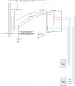
JN has good advice. The break in the coax shield and coupled thru with a small value cap is inside the house... well past the coax's earth ground outside the home. It has the isolation cap in series with the coax shield at the end of your coax inside the home..... at the end going to your STB or modem.
If you do not do this, when you connect your CATV A-V together, there can be a new parallel ground path from gear using a 3-pin plug with a ground pin plugged into your wall outlet which goes back to earth at the ac panel's grounding. As for lightning, this new path is a much better path to ground thru your gear than the higher R earth path.
Can everyone visualize this without drawing?
THx-RNMarsh
Last edited:
Richard,
That is something I could get from Fry's? Just a cap coupler for a 75 ohm cable connection? I know the TV and the cable modem share the same drop to the house so I'll go look in the box and see if there is any isolation at all there from the incoming signal cable.
That is something I could get from Fry's? Just a cap coupler for a 75 ohm cable connection? I know the TV and the cable modem share the same drop to the house so I'll go look in the box and see if there is any isolation at all there from the incoming signal cable.
In the US, on the east coast
Well, off grid, plastic well hose so bonding to the cold water pipe is a placebo, pretty simple solar setup, and a near miss toasted two $750 inverters. I later found out the grounding rod was about 12" into the soil because of ledge.
BTW A mile off coast no grid and all the inverters generate enough spew that all the EMI precautions are still needed.
Last edited:
- Status
- Not open for further replies.
- Home
- Member Areas
- The Lounge
- John Curl's Blowtorch preamplifier part II