Make this simple-
Pick an appropriate alloy, wind it in a noninductive form, expose it to RF and heat it to the curie point. The additional heat from the signal passing orthagonally won't change the temperature because of the Curie threshold.
Or use a JJ array resistor, which operates very close to absolute zero but its very predictable.
(Talk about going off the rails. . . getting to -140 dB THD should be possible with none of this nonsense. May not be possible with tiny surface mount parts but its not difficult to work out solutions.)
"If you build it they will come..."
But has SY compared a -120 db amp to a -140 db one?
And then they will love the -36dB one above all.
I think most of the time, unless the device temperature coefficient itself is a strong function of temperature, the notion that higher quiescent temperatures reduce the effects of signal-induced self-heating is a misconception, albeit intuitively plausible.
If one is working at very low temperatures where carrier freezeout starts to occur (say below 100K in conventionally-doped silicon) then it is a very different story. For example 77K (liquid nitrogen, hence very convenient as such things go) is a very poor temperature for operation of silicon JFETs.
Brad Wood
GASFET's do fine,IEEE Xplore - Abstract Page
20K noise temperature at 500MHz not bad.
Yes GaAs and even germanium do well, although their excess noise (as FETs) are not very good at low frequencies.
Nakamura (iirc) did a Ge JFET nuc sci preamp that worked pretty well at 4.2K, many many years ago.
The $10K that Mr Sutherland charges for a twin case phono stage with low part count is more mind-boggling, imo.
+20 years ago, Avantgarde in Switzerland came out with an add-on battery PS for the MAS (Metaxas) preamp they distributed in Europe.
Bumped up the price of the pre considerably, and base retail wasn't exactly cheap to begin with. *
PS design has evolved in 20 years time, and batteries by no means deliver clean DC.
For a phono stage that has to stay under $1k retail, batteries may be a/the cheaper solution.
(* couple of years later, Mr Gassmann of Avantgarde, came out with an all-battery phono/pre/power amp combo under his own brand name. The powersupply of the power amp carried an automatic charging circuit, plus 8 Sonnenschein batteries of a size used for motorcycles. Total cost ~45K Swiss Francs in the early '90s. Afaig, Mr Gassmann still has the hots for batteries, his latest XA preamp, in a truly beautiful cast-alloy case, runs on can juice also)
Yes Fred did lot of work for this amps. I remember that every unit from Kostas Metaxas sounded slightly different and Fred Grassmann changed all the transistors before he delivered the amps.
The Avantgarde amps sounded quiet well but I never got involved into the music, the spark never jumped over. Anyway, Fred is a nice person to have good conversation. Is he still in business?
Demian,
I was looking for my results with DC bias to see if the 3rd harmonic changed, but did not find it. I do think I posted it way back on this thread.
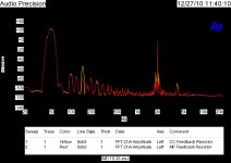
But I did find one interesting test that I may not have shown before. 2 KHz & 50Hz IMD using the same everything except feedback resistor.
BTY if you know of any -140 db amplifiers I'd be curious. (-140 IM @ say 1KHz -30 and .03 Hz -3.)
ES
I was looking for my results with DC bias to see if the 3rd harmonic changed, but did not find it. I do think I posted it way back on this thread.
But I did find one interesting test that I may not have shown before. 2 KHz & 50Hz IMD using the same everything except feedback resistor.
BTY if you know of any -140 db amplifiers I'd be curious. (-140 IM @ say 1KHz -30 and .03 Hz -3.)
ES
Attachments
Last edited:
pretty trivial at consumer line levels - 2 op amps in a multiloop
sub regulate the input op amp supplies, use modified integrator local feedback around the output (CFA) op amp and the input op amp only swings mV into 100s kOhm/pF driving the output op amp
it is easy to get to the point that common mode input device nonlinear currents are the biggest identifiable active device issue left - if you can use inverting mode or have low source Z you're done
and even Doug Self now shows how to treat the input current nonlinearity
have you seen this passive device distortion in large Bulk metal Foil R? - I didn't see any in common metal film with 10kHz+11kHz IMD test - maybe too high for the thermal time constants
Last edited:
Are the yellow sidebands on 2kHz at +- 50Hz or +- 100Hz? If the latter, this would tie in with more yellow 150Hz but little 100Hz. CC gives more 3rd order.
If you expand the image fully you can see the 50, 100, 150 and 200 Hz sidebands!
Well Ed Simon, you have made it very clear why we have to take care as to what feedback resistor we use.
Just to remind everybody, I have been 'harping' about differences in resistors for more than a decade, especially with the feedback resistor, as it is the 'template' that the amp tries to model itself on. Usually to much 'laughter' as well. Well, now it should be clear, VERY clear. '-)
Just to remind everybody, I have been 'harping' about differences in resistors for more than a decade, especially with the feedback resistor, as it is the 'template' that the amp tries to model itself on. Usually to much 'laughter' as well. Well, now it should be clear, VERY clear. '-)
Demian,
BTY if you know of any -140 db amplifiers I'd be curious. (-140 IM @ say 1KHz -30 and .03 Hz -3.)
ES
Ed,
Can you be more specific here? Maybe I missed something. Are you talking about a power amplifier? What kind of IM are you talking about? Two tone? SMPTE? Or did you mean to be talking about 1 kHz THD?
Cheers,
Bob
There's a company that has been testing and categorizing silicon for dc to dc conversion at 77k. Power as well as smart stuff. The purpose of conversion at 77k is to eliminate the warm to cold transition heat loss of very large copper conductors required for 5 or 10 kiloamp operation. If they can use a kilovolt or 2 and drop the current to 50 amps, the refrigeration expense goes down.
John
Ed,
Can you be more specific here? Maybe I missed something. Are you talking about a power amplifier? What kind of IM are you talking about? Two tone? SMPTE? Or did you mean to be talking about 1 kHz THD?
Cheers,
Bob
Bob,
IM dual tone, one at .03 Hz at a power level of -3db re full power, the other 1 KHz around -30db re full power. Just for you you can also try it at 20 KHz.
")
Yes I meant a power amplifier. Now most can't handle .03 Hz so you may have to run up the frequency a bit, but that will result in lower distortion.
The issue I have been playing with as shown by the two measurements of the same resistor comparisons is that the envelope of a musical note (often mentioned as ADSR) can cause shifts in amplifier performance. The question has become, are there forms of transient distortions (ex. once every 1000 seconds!) that are missed in testing but are large enough to be detected by an experienced listener?
ES
And just to be a B... show the same levels of distortion at the real operating point say one watt!
but you say you don't find bulk metal foil - arguably the technical best to be the audible best - hows that square with you "I never add distortion" claim?
Others measure better on third order distortion. Low tempco is nice low and linear is better.
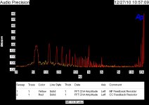
Simon,As you can see from this 19 & 20 KHz IM plot, it is the low frequency modulation that makes the CC & MF perform significantly differently.
I find it difficult to interpret measurements in your second picture.
After zooming in, one can see that yellow trace is always underneath the red one, which means almost the same spectral content.
Yellow trace shows, what appears to be, higher noise floor in 20Hz-1kHz region, but according to text notes, yellow is MF. Is that correct?
Best,
Simon,
I find it difficult to interpret measurements in your second picture.
After zooming in, one can see that yellow trace is always underneath the red one, which means almost the same spectral content.
Yellow trace shows, what appears to be, higher noise floor in 20Hz-1kHz region, but according to text notes, yellow is MF. Is that correct?
Best,
That is correct. Although they seem to be about the same below 40 and back by 250 Hz.
Last edited:
- Status
- Not open for further replies.
- Home
- Member Areas
- The Lounge
- John Curl's Blowtorch preamplifier part II