Some of the class-D chips I've seen don't include the output power devices, but only everything up to the driver stage.I would not really go for 600W with more than 40W power dissipation on that tiny chip.
That seems like a more robust approach for high power, as the output MOSFETs can have more thermal contact area and heatsinking than a single small surface-mount chip can.
I think some of the higher-power SURE modules sold by Parts Express have this topology.
-Gnobuddy
I suspect these are based around IRS... driver chips. This may be the way to go if your target is above say 150W. On the other hand - the monolithic design has its advantages. For instance how will you provide an overtemperature shutdown with discrete power MOSFETs?
With TPA3255 I tested overtemperature shutdown by pushing it with removed heatsink. The AVR-microcontroller restarted automatically as soon as temperature was in range. Under that condition the amp turned on-off-on-off within seconds with nor harm at all. Try this with discrete PowerMOSFETs...
With TPA3255 I tested overtemperature shutdown by pushing it with removed heatsink. The AVR-microcontroller restarted automatically as soon as temperature was in range. Under that condition the amp turned on-off-on-off within seconds with nor harm at all. Try this with discrete PowerMOSFETs...
I got a few UF4007 fast high-voltage diodes today. I think I have all the parts needed to start tinkering with KMG's faux-triode circuitry now. We can't let mjd_tech have all the fun!
In other news, the "2BJTE" distortion circuit is half-built on my breadboard, but I haven't found the time and energy to finish and test it. Update coming soon, I hope.
-Gnobuddy
In other news, the "2BJTE" distortion circuit is half-built on my breadboard, but I haven't found the time and energy to finish and test it. Update coming soon, I hope.
-Gnobuddy
The fun continues...I got a few UF4007 fast high-voltage diodes today. I think I have all the parts needed to start tinkering with KMG's faux-triode circuitry now. We can't let mjd_tech have all the fun!
-Gnobuddy
This time I decided to listen to a valve AB763 reverb channel, just the preamp, not the power amp stage. I used my "champ" clone, which has the classic reverb channel straight into a single ended 6V6.
First, I breadboarded an LND150 source follower, so I can tap off the 3rd gain stage of the AB763 preamp and drive a low impedance load. I disconnected the amp's speaker and attached a dummy load, I don't want to hear the 6V6, or the guitar speaker, but you can't just disconnect the speaker, you need a dummy load. I didn't want to mess with the circuitry in the amp, just tap off the plate of the 3rd stage.
Note, this amp, when played normally through its speaker is crisp and tight with a very nice Champ breakup when cranked. DC powered preamp filaments, extra B+ filtering, star grounded everything, a darn good sounding amp if I do say so myself.
So, now it is set up to hear just the preamp.
I connect the source follower and hook it up to the headphone amp.
I want the brutal honest truth.
Plug in the same telecaster as I've been using, put the headphones on.
So, do I hear the clean crisp tight sound that I get when playing this amp normally?
The answer is, a resounding NO.
Flubby, anemic sounding dreck with a nasty patina of fizz.
Sounds like plugging a guitar into an MXR distortion + into a home stereo system.
So, what was the point of this experiment?
Well I had rebuilt the KMG style preamp on terminal strips, star grounding, extra B+ decoupling. So no more solderless breadboard.
The sound was cleaner, but the fizz remained.
I wanted to see if the fizz problem was a "solid state" problem, or if the actual 12AX7 stages did the same thing.
Well they do, KMG's gain stage emulates the 12AX7 behavior quite well.
In fact, listening to both preamps, and ignoring the fizz, I prefer the solid state version over the actual valve version, but this could be due to differences in the gain structuring, the solid state version having a bit more gain overall.
I'm not going to pull my hair out agonizing over the fact that fizz is being generated.
I have confirmed that 12AX7s do indeed fizz themselves, and that in practice, the output stage and guitar speaker filter out a lot of the dreck.
The next step is to build some kind of speaker emulation with at least a 4th order lowpass filter. I'll need to re-read some of the previous posts in this thread...
Also, I have confirmed that you do not need separately buffered negative power supplies.
You can run the KMG gain stages in fixed biased mode, with a simple positive supply derived from a 270k/2k7/10uf voltage divider off the B+ rail. At 300V this produces roughly +3V. This rail can feed at least 3 gain stages. A negative supply is an option too if you want to go that route. I tried it, just a single supply, not individually buffered, didn't notice any difference, and went back to fixed bias, as it is simpler.
You do not need a regulated B+. The gain stages work well with B+ from 250-320V. I have not tried other voltages, other than when bringing the variac up slowly. I would expect you can use a lower B+ voltage, say 150V, but I think the "+3V" rail needs to be pretty close to +3v for the gain stages bias correctly. Of course, you'd get less headroom at 150V and possibly the gain would be different (probably less).
Oh, also, I messed around with putting two 12V wall wart transformers back to back to create a "poor man's" isolation transformer.
It didn't work out. I think there is some kind of fuse or thermistor or something in the primary windings of these things, that adds a lot of series resistance.
It's no big deal when using it as intended, but it is a problem when using it "backwards" Also I think the cores were saturating, even under a small load of 5mA.
I didn't pursue it any further. I think a couple of "filament" transformers would work for this, but not little wall wart transformers.
Sounds as though they need to start wearing Depends.12AX7s do indeed fizz themselves

I had trouble falling asleep last night, so I spent some quality time with LTSpice, tinkering with ideas for a speaker emulation filter.The next step is to build some kind of speaker emulation with at least a 4th order lowpass filter.
For som decades now, engineers have been trained to immediately head for a fistful of op-amps as soon as they hear "analogue active filter". There is no doubt that op-amps will precisely and accurately do what they're told to, and produce textbook filter responses.
However, I built my de-nastifying filter with discrete transistors and JFETs, because some of us suspect op-amps are too precise and accurate when it comes to electric guitars; it appears that electric guitars are best seen through rose-coloured spectacles, or rather, best heard through soft and flattering amplifying devices.
Ever since the BC147/148/149 and BC 157/158/159 families arrived decades ago, they have been a delight to use - excellent performance, no stability problems, and very inexpensive, too. So last night, my LTSpice tinkering was based around using discrete BJTs, more modern descendants of the old BC148. These have more than enough gain and speed to provide excellent performance in the kind of filters we want for guitar speaker emulation.
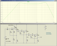
The attached screenshot shows what I came up with before I went to bed last night. It produces the frequency response we want when fed from a voltage source in LTSpice; to work with real-world source impedances, it needs a buffer stage added to the input (i.e. one more transistor.)
To be clear: this filter produces a second-order high pass filter response with a corner at around 100 Hz, and a mild peak of about 3 dB, simulating the bass response of a typical guitar speaker in an open-back or sealed cab.
The filter also produces a slight peak of about 4 dB at 3 kHz, followed by a steep fourth-order treble rolloff.
Experimenting with my graphic EQ, I found 3 kHz was the magic frequency that most affects the high treble from a guitar. Turn it down for smoothness, turn it up for a bit of brightness, turn it up a bit more for "bite". This is going to be very subjective, and very dependent on the type of guitar being used. My choice of a 4 dB peak was therefore pretty much as stab in the dark. (Just like buying a new $150 guitar speaker...)
While adding an input buffer is all it would take to complete this filter design and make it work as intended, it occurred to me that alternating NPN and PNP transistors would largely cancel out the four 0.7 volt Vbe drops, and would be a slightly more elegant design as a result. When I get a little time I'll draw up the few rather slight changes that would require.
By the way, I built input, buffer, notch, and treble-rolloff filters of my de-nastifying filter (4 BJT stages) onto one half of a tiddly little proto-board, in a total board area of maybe 3 square inches. I expect this speaker emulation filter would, with some care, fit on a similar area of proto board.
I think one intriguing experiment would be to try half the B+ (150V), and half the number of Schottky diodes (two) in the source network, along with half the drain resistance (say 47k instead of 100k).I would expect you can use a lower B+ voltage, say 150V,
<snip>
Of course, you'd get less headroom at 150V and possibly the gain would be different (probably less).
The idea is that halving the number of Schottky diodes would roughly double the transconductance, while halving the drain resistor would bring the gain back down to the same value as before. In principle, this should then feel and respond the same way to the guitar as before.
Half the B+ and half the (drain) resistance should also bring back the DC operating point to maintain about the same headroom with the halved 150V B+.
As a bonus, output impedance would be lowered to 47k, which is a lot closer to the output impedance of an actual half-a-12AX7 with a 100k anode resistor.
If it all works out as think it might, these changes should produce the same results as the 300V version, but at a friendlier 150V B+, and using fewer components per stage.
Of course it's entirely possible that I might be quite wrong, so this needs to be verified by experiment!
This is exactly the same thing I've read over and over again on the 'Net about this particular configuration. I've also read explanations as to why from a few people who appear to know what they're talking about.Oh, also, I messed around with putting two 12V wall wart transformers back to back to create a "poor man's" isolation transformer.
It didn't work out.
<snip>
I think the cores were saturating, even under a small load of 5mA.
In a nutshell, apparently small power transformers are quite inefficient, and draw a lot of no-load magnetizing current. Typically the second transformer in the chain (the one stepping-up voltage) will draw enough magnetizing current to overload and overheat the first transformer in the chain ( the step-down one.)
Some people have made it work by using a much larger transformer as the first one in the chain (the step-down one). But it's still a rather ugly kludge, and you still have to deal with the size, weight, and bulk of two transformers rather than one.
A Triad N48-X is $14.25 (USD) from Mouser, hardly a king's ransom, so it is hard to justify the much more trouble-prone use of a pair of back-to-back small power transformers. If you need 230V AC instead of 120, the Triad N68-X is less than two bucks more, $15.81 USD from Mouser.
-Gnobuddy
Attachments
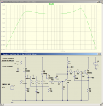
I updated the speaker emulation filter in my previous post - I've added the input buffer, and a PNP stage to maximise headroom (all emitters are very close to 9V, the midpoint of the 18V supply voltage.)
DC coupling where possible minimises the number of biasing resistors and coupling capacitors.
Here is a screenshot, as well as the LTSpice .asc file for your tinkering / tweaking pleasure.
There is nothing sacred about the 18V supply voltage. It can be raised if desired (with maybe some resistor value changes.) The transistors can cope with 40V.
-Gnobuddy
Attachments
There was a recent thread on diyAudio about a 600 W (!!) TI class-D audio power amp evaluation board that was selling (during a half-price sale) for something like $80 (USD).
It was $75 pus $6 shipping. For another $50 they offered a guitar preamp. Loud, really loud, but I would rather play a big tube amp.
I would not really go for 600W with more than 40W power dissipation on that tiny chip.
I beat that thing pretty hard on 50 volts with music and the guitar preamp. It didn't get that hot
The TI class D amp is an experiment. I am planning some big tube amps, and will do some comparative testing with both music and musical instruments (synth and guitar).
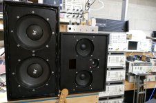
DIY speakers of course! The pair shown here are known as "loud" and "louder." They were both budget builds. another bigger slightly higher budget set is coming.
The EV speakers were an impulse purchase on the opening day of the "Mars Music Mega Store." I went there with a friend who waited in line outside for a couple of hours to get his guitar autographed by Randy Bachman while I wandered the store and bought stuff. Mars was the brainchild of the owner of Office Depot who bought the historic Ace music store in Miami and attempted to franchise Mars with a bunch of his own money......it failed and I would find myself shopping the "going out of business sale" a few years later.
Loud on the right has a pair of cheap Parts Express PA165-8 drivers and a cheap bullet tweeter crossed with 3 X 1uF mylar caps in parallel. A switch turns the tweeter off for guitar use.
I built two of these speaker cabinets for testing amps using cheap drivers so I wouldn't cry if I blew them up. The box was simulated and designed to give flat response down to 70 Hz. The small drivers are almost 93db efficient and get quite loud. What surprised me is the quality of the sound for HiFi listening. The digital piano sound in my old Roland JV1000 sounds spooky real through these.
I have used them outdoors as PA speakers for a rock band handling keyboards (direct), guitar (miked amp) and vocals. The bass player and drummer provided their own loud. I fed them with a 125 WPC tube amp and they played for several hours without incident.
Each cabinet presents a 4 ohm load. The TI amp with a big 48 volt SMPS turned up to 52 volts makes 150 to 200 WPC according to the data sheet. I did not bench test it yet. I played the TI through those speakers for "HiFi" music testing. It gets way too loud before distorting. I fed it some Pink Floyd and other bass heavy music for a while and one of the speakers started sounding funny.....OK, I finally blew a speaker.......Nope, the drivers had rattled all the mounting bolts loose.
Dayton Audio PA165-8 6" PA Driver Speaker
Louder is a single large heavy box containing a pair of 1980's vintage Electro-Voice EVM 10M guitar speakers. The sticker on the back of each driver says "8 ohms 200 watt." I have each driver wired to its own jack so that they can be driven with a stereo amp. I made this speaker cabinet in the 90's when National first came out with the high power amp chips. One chip for each 8 ohm driver driver made more power than one chip on a 4 ohm pair.
I connected this cabinet to the TI board with one driver on each channel, maybe 125 watts per speaker. I used TI's guitar board which does clean reasonably well through these speakers, but gets nasty quick when you use the drive channel and turn the guitar all the way up. The EV speakers are 100 db efficient, so they are louder than the 6 inch speakers even though the power is lower, and sound better when driven with a guitar. They suck for music reproduction though.
I have a pair of these drivers waiting for time and weather to allow me a day or two of table saw time to catch up. The plan is for a single sat of cabinets for the 15 inch woofer (rated for 500 watts RMS, 1KW peak) and a second cabinet set for the Faital Pro 6FE200 and JBL ST200 tweeter.
Dayton Audio PA380-8 15" Pro Woofer
FaitalPRO 6FE200 6" Professional Midrange Speaker 8 Ohm
Selenium ST200 Super Tweeter
What kind of speakers do you push with that enormous power?
DIY speakers of course! The pair shown here are known as "loud" and "louder." They were both budget builds. another bigger slightly higher budget set is coming.
The EV speakers were an impulse purchase on the opening day of the "Mars Music Mega Store." I went there with a friend who waited in line outside for a couple of hours to get his guitar autographed by Randy Bachman while I wandered the store and bought stuff. Mars was the brainchild of the owner of Office Depot who bought the historic Ace music store in Miami and attempted to franchise Mars with a bunch of his own money......it failed and I would find myself shopping the "going out of business sale" a few years later.
Loud on the right has a pair of cheap Parts Express PA165-8 drivers and a cheap bullet tweeter crossed with 3 X 1uF mylar caps in parallel. A switch turns the tweeter off for guitar use.
I built two of these speaker cabinets for testing amps using cheap drivers so I wouldn't cry if I blew them up. The box was simulated and designed to give flat response down to 70 Hz. The small drivers are almost 93db efficient and get quite loud. What surprised me is the quality of the sound for HiFi listening. The digital piano sound in my old Roland JV1000 sounds spooky real through these.
I have used them outdoors as PA speakers for a rock band handling keyboards (direct), guitar (miked amp) and vocals. The bass player and drummer provided their own loud. I fed them with a 125 WPC tube amp and they played for several hours without incident.
Each cabinet presents a 4 ohm load. The TI amp with a big 48 volt SMPS turned up to 52 volts makes 150 to 200 WPC according to the data sheet. I did not bench test it yet. I played the TI through those speakers for "HiFi" music testing. It gets way too loud before distorting. I fed it some Pink Floyd and other bass heavy music for a while and one of the speakers started sounding funny.....OK, I finally blew a speaker.......Nope, the drivers had rattled all the mounting bolts loose.
Dayton Audio PA165-8 6" PA Driver Speaker
Louder is a single large heavy box containing a pair of 1980's vintage Electro-Voice EVM 10M guitar speakers. The sticker on the back of each driver says "8 ohms 200 watt." I have each driver wired to its own jack so that they can be driven with a stereo amp. I made this speaker cabinet in the 90's when National first came out with the high power amp chips. One chip for each 8 ohm driver driver made more power than one chip on a 4 ohm pair.
I connected this cabinet to the TI board with one driver on each channel, maybe 125 watts per speaker. I used TI's guitar board which does clean reasonably well through these speakers, but gets nasty quick when you use the drive channel and turn the guitar all the way up. The EV speakers are 100 db efficient, so they are louder than the 6 inch speakers even though the power is lower, and sound better when driven with a guitar. They suck for music reproduction though.
I have a pair of these drivers waiting for time and weather to allow me a day or two of table saw time to catch up. The plan is for a single sat of cabinets for the 15 inch woofer (rated for 500 watts RMS, 1KW peak) and a second cabinet set for the Faital Pro 6FE200 and JBL ST200 tweeter.
Dayton Audio PA380-8 15" Pro Woofer
FaitalPRO 6FE200 6" Professional Midrange Speaker 8 Ohm
Selenium ST200 Super Tweeter
Attachments
Gary Kildall of Digital Research (originally called "Intergalactic Digital Research"!) did blow off IBM. When the IBM entourage came over to visit him and discuss terms, he was out flying his plane.I'm highly amused at the brand name! The owner of the "original" company of that name wrote CP/M, the first microcomputer operating system (of any popularity), and infamously blew off (I forget which, maybe both - these computer history stories are so incredible but true) Bill Gates and IBM.
Bill Gates' mother happened to have a lot of influence at IBM - I think I heard she was on the board. So Mama Gates suggested they talk to her son, as he had a lot of expertise in the microcomputer field. Bill bought the rights to a quickly hacked proof-of-concept OS called QDOS (Quick & Dirty Operating System) from Seattle Scientific, and then made improvements, creating MS-DOS/PC-DOS.
OK, that's enough of the off-topic stuff. I'll go back on topic now. Personally, I think using real tubes is a lot easier than trying to emulate them with incredibly complex solid state circuits. There, I said it!
See post #416.Gary Kildall of Digital Research (originally called "Intergalactic Digital Research"!) did blow off IBM.
<snip>
Bill bought the rights to a quickly hacked proof-of-concept OS called QDOS (Quick & Dirty Operating System) from Seattle Scientific (actually Seattle Computer Products)
I agree with you about real valves being easier for home DIY. However, did you forget our earlier discussion about fake butter, and why I (and many other people) buy it?Personally, I think using real tubes is a lot easier than trying to emulate them with incredibly complex solid state circuits.
For home DIY, yes, I agree, using a single triode and three or four resistors and caps is easier than trying to emulate one with a JFET. (But building the high-voltage power supply is enough to scare off many, many people.)
The real valve might very well sound better too, we're still trying to decide on that one.
Easier or not, better sounding or not, it may still not be the right solution for other reasons. In the case of my recent project described in this thread, using real valves would have caused too much expense for me, and too much weight and bulk for the intended owner of the amp, who is disabled and walks with two canes.
The amp I eventually built had all the electronics contained in a space barely 2 inches thick. The heaviest part of the electronics was the power brick, and that weighed ten times less than an old-fashioned 60 Hz transformer of equivalent power capability. The actual preamp and amp only weighed a few grams each. Power output was around 25 watts RMS total. Combined, these specs simply could not have been met with real valves.
Let's get back to your "easier" comment. For DIY, a real triode and a fistful of passive components is easier. But for a commercial manufacturer, stuffing a few MOSFETS and Schottky diodes into a PCB using an automatic parts placement robot is far, far easier than stuffing in a valve socket, and having to deal with fragile, expensive, hot, bulky glass bottles.
I'm shocked that no commercial manufacturer has licensed KMGs work and run with it - I think they've missed a real opportunity there. While perhaps costlier than the DSP approach, KMG got better results with his analogue circuitry than the vast majority of commercial digital DSP offerings out there, many of which still sound pretty bad, even in 2018.
And let's not forget that KMGs circuitry could be built into an integrated circuit, if someone had the money and mindset to make it happen. This could really revolutionise the affordable end of the guitar amp market, creating surprisingly realistic "tubey" guitar amps using extremely inexpensive solid-state components.
Unfortunately, the industry has gone in the direction of "One hundred and fifty awful kazoo sounds in one box!" rather than "One great clean, and one great overdriven sound in one box!", so we are unlikely to see this happen.
And you won't get any disagreement from me, either!There, I said it!
I had exactly the same reaction the first time I stumbled across KMGs work, which was some years ago. In fact I dismissed it out of hand, put the whole thing out of my mind, and forgot all about it, until Printer2 brought it up again in this thread.
This time around, my mind was already focused on the fact that I had to build a solid-state amp, and I wanted to make it sound as good as possible. In that frame of mind, I was more receptive to KMG's work.
If you've read through the thread, and are familiar with some of the member names, you may know that many of the people posting here - Tubelab, Printer2, mjd_tech, myself, many others - also build stuff using real glass-and-metal valves or "toobs".
The world of guitar amps is filled with possibilities. Valve only? Great, interesting, and it's been done for the past ninety years or so. There is little room for improvement, it's a mature engineering field with no new developments.
Solid-state only? Great, interesting, and it's been done (mostly badly) for at least the last fifty years. There is still lots of room for improvement. A lot of this thread has been about exploring this.
But to me, the most interesting, and most unexplored, route is hybrid designs, that mix and match valves and solid-state devices in ways that use each one to its best strength.
We've actually had surprisingly little discussion about hybrid circuitry on this thread (just a little from George), but perhaps that will change in the coming days and weeks.
In a nutshell, the philosophy of this thread is, at least in my mind, to develop ways to get good guitar sounds using whatever device you happen to want to work with.
If we are lucky, we will end up with some improvements over all-valve amps as well. For example, traditional passive guitar tone controls are truly awful, and desperately in need of improvement. Converting them to active controls makes them behave much better, but using real vacuum triodes for this is expensive, hot, and bulky. The obvious engineering solution is to use MOSFETs to create good active guitar tone controls - but this approach has been held back commercially because of the prejudices of guitarists who hate all solid-state devices, whether or not there is a good reason to do so.
I will say that, for me, one of the best, and certainly easiest to use, guitar tone controls I've ever encountered is the one I developed for my recent amp project: the combination of an active FET tilt control, and the active de-nastifying filter with its 800 Hz notch, slight bass boost, and speaker emulation.
That took six active devices - very expensive and impractical with real triodes, but cheap, compact, and quite easy with the little JFETs and BJTs I used. Not as simple as Leonidas' awful "tone stacks", but such a huge improvement!
Let go of the "Valves only!" comfort-blanket, AquaTarkus! You are way too smart to be held back from all the fun to be had working solid-state devices into great guitar amp circuitry, with or without real valves sprinkled into the mix!
-Gnobuddy
I want to get something sounding reasonably good and that is lightweight. I am going to try a tube preamp with a PWM amp, an all SS amp and a tube amp using a brick and a voltage booster for the supply. Spending a few hours on the Hundred Buck Amp I am not jumping in until I finish the projects on the go now. I don't want them to collect dust for a year.
I've never heard LTSpice called "incredibly complex solid state circuits" but whatever.OK, that's enough of the off-topic stuff. I'll go back on topic now. Personally, I think using real tubes is a lot easier than trying to emulate them with incredibly complex solid state circuits. There, I said it!
The KMG "triode" requires an LND150, 2 resistors, and 6 diodes. That's 9 components. It needs a B+ of roughly 300V and either a -3 or +3 supply. This sounds like a lot, and it is.
However real valve amps have multiple supply voltages too, B+ and 6.3vac filament at minimum and optionally 5vac filament and a negative fixed bias supply.
What I did was build those 9 components on a little perfboard "module", with 3 eyelets for "cathode" "grid" and "plate".
Once you do that, it doesn't seem so complicated anymore. You just treat the module like it was an actual triode and you can use the same layout techniques you would use for a "toob" circuit.
The standard Fender tone stack leaves a lot to be desired from an engineering standpoint. It has a lot of insertion loss, a fairly heavy load on the preceding gain stage, and not very frequency selective. The thing is, it's economical, familiar, and easily tweakable, for instance: switchable treble and mid caps.
I did try a 3 band active Baxandall type EQ one time, driven by a JFET/MOSFET cascode. It didn't work out as well as I hoped. There were more unusable settings than the standard stack. It just didn't seem worth the extra component count, compared to the standard stack with switchable caps, which I find gets the job done good enough.
So my inclination is to go with the standard passive tone stack, combined with active "de-nastifying" filtering.
I am assuming Gnobuddy's speaker emulation circuit (post #485) requires high Beta transistors. I'm fresh out of BC550C at the moment and not sure if I have anything else with that high Beta. Not sure if 2N3904 or MPSA06, which I do have, will work correctly.
Of course, I can just use opamps, but would like to try transistors.
Also, I haven't seen much mention of state variable filters in the context of speaker emulation. Any thoughts? I built an "Anderton Super tone control" many moons ago, and while many of the settings were too weird for practical use, I was impressed with the state variable filter as a building block.
My gripe with it is from the usability end of things. Turning any one knob causes changes over the entire frequency spectrum. The response of the controls is also very nonlinear, a ten-degree rotation around the 7-o-clock position produces a very different change than the same ten-degree rotation around the 3-o-clock position.The standard Fender tone stack leaves a lot to be desired from an engineering standpoint.
If you think back to your first encounter with the Fender tone stack, particularly the 3-knob one, you probably had to spend some time learning how to use the tone controls to get the sound you wanted. And if you listen to live guitar music, you often get the sense that some guitarists never did figure out how to set the darn thing to get an agreeable sound.
Interestingly enough, the active one-band (tilt) tone control worked far better than I'd hoped!I did try a 3 band active Baxandall type EQ one time, driven by a JFET/MOSFET cascode. It didn't work out as well as I hoped.
The entire guitar frequency band (say from 80 Hz to 5120 Hz) is only about six octaves wide. I think this might simply be too narrow to cram a 3-band tone control with +/- 6 dB/octave slopes into. If you try, you get lots of unwanted interaction (overlap) between controls, and/or a limited amount of control.
The situation is easier for Hi-Fi, where you have ten octaves to play with between 20 Hz and 20 kHz.
For guitar, one solution seems to be to use fewer control knobs; in LTSpice, it looks as though an active 2-band Baxandall will work well without unwanted control interaction. Another solution is to use higher-order filter slopes, like the graphic EQs used in a few brands of high-gain guitar amps.
I'm not so sure. Since only unity voltage gain is required for these Sallen-Key filters, I don't think great demands are placed on the transistors. I suspect low beta transistors will work just fine.I am assuming Gnobuddy's speaker emulation circuit (post #485) requires high Beta transistors.
If beta is much lower than the 500+ of a typical BC550C/BC560C, it might be necessary to lower the values of R13/14 and R9/11, in order to supply the increased base current requirements.
I posted the LTSpice .asc file in post #426. Please feel free to download and tinker with it. Transistor swaps are just a few mouse clicks away!
Which reminds me, I forgot to attach the BC550C.txt and BC560C.txt files earlier. If anyone wants them, let me know, and I'll attach them to a later post. I don't have access to my home sim files at the moment.
I built a guitar preamp design published in Elektor magazine in the 1980s, that used a state variable filter as a tone control. It used three or four opamps in the tone control alone.Also, I haven't seen much mention of state variable filters in the context of speaker emulation. Any thoughts?
It worked fine as I recall, but I was a novice guitarist at the time, and really didn't have the skill or experience to tell a good tone control from a great one. Also, I hadn't discovered the magical marriage of valves and guitars yet at that time, so pretty much everything I played sounded awful, good tone control or not!
I was, too. IIRC the state variable filter in that Elektor preamp provided lowpass, highpass, and bandpass responses, and the outputs of any combination of those three could be mixed together to provide a variety of frequency responses.I was impressed with the state variable filter as a building block.
I also remember that adding one more op-amp wired as a differential amplifier creates a band-stop (notch) filter response as well. This wasn't part of the Elektor design, though.
-Gnobuddy
I hope you've noticed that some of us have also built real wire-and-silicon circuits in this thread.I've never heard LTSpice called "incredibly complex solid state circuits" but whatever.
I don't use LTSpice at all when I'm trying to create a new valve circuit - in my limited experience, valve simulations are so inaccurate as to be worthless for my purposes.
But when I'm trying to create something like the four-transistor speaker emulation filter I posted recently, I find LTSpice invaluable. I can't visualize the complex-number polynomials that describe filter frequency responses in my head; much better to let LTSpice figure out and display the frequency response for me, so I can then tweak component values until I get the frequency response I was aiming for.
Coming from solid-state circuits to valve circuits for the first time, I had the opposite reaction to AquaTarkus. I could not believe how simple the classic valve guitar amp circuits were.
When I built a solid-state power amp, it would typically have Darlington pair outputs, current source loads and sinks, maybe a dozen transistors, and be DC coupled throughout.
Then you look at a valve guitar power amp, and there are two power valves and one dual triode in the entire thing, all AC coupled, with just a handful of passive components sprinkled around. And what are these strange heavy lumps of iron called "output transformers"?
It makes sense, of course, considering the chronological sequence: classic valve guitar amps are a look back into the pre-history of modern electronics, like finding a stone axe in an early hominid settlement, and comparing it to a contemporary chrome-steel kitchen knife.
The surprise for me was that the stone axe turned out to be a better instrument than the modern chrome-steel kitchen knife. At least when it comes to electric guitars, if you'll pardon a major mixing of metaphors!
Perhaps that's why I have an interest in hybrid guitar amp designs. It's very evident that valves and transistors have complimentary strengths and weaknesses, so marrying them together should produce some very good results.
-Gnobuddy
When my buddies needed a quick guitar amp we pulled out a Lil' Tiger for a big 15W. surprisingly good sounding clean to dirty. Limited NFB and a simple circuit. We did have a problem blowing the outputs though, it was not designed for band use. Had a bag of replacements and got it going again in no time.
Attachments
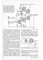
The Li'l Tiger was the key building block of my first foray into solid state guitar amp building when I was in high school (67 - 70). It was affordable and you could power it with transformers available at Radio Shack. My first one used a DIY preamp whose schematic came from tracing out one of the popular SS guitar amps of the day. It used all discrete transistors. The speaker was a 15 inch field coil monster pulled out of an old organ. I ran the field coil on rectified and filtered wall outlet. The frequency response went low enough that smacking the guitar strings could bottom out the speaker's voice coil. This amp had a reverb tank and a surf guitar sound that I would have died for 3 or 4 years earlier, but surf music had fallen out of fashion.
In 1973 I got a job at Motorola and found several people also interested in making similar stuff. We made dozens of several flavors of Tigers for use in guitar and HiFi amps. The Plastic Tiger and Universal Tiger were our go to circuits for about 10 years.
After blowing the Lil Tiger a few times we stuffed bigger parts in. I don't remember what they were, but I think they were from TI. We built some Plastic Tigers with off board output parts mounted on heat sinks with short wires. Again they were not the stock parts and used a slightly different package. They rarely blew, and the blown ones were usually from a shorted speaker connection.
In 1973 I got a job at Motorola and found several people also interested in making similar stuff. We made dozens of several flavors of Tigers for use in guitar and HiFi amps. The Plastic Tiger and Universal Tiger were our go to circuits for about 10 years.
We did have a problem blowing the outputs though
After blowing the Lil Tiger a few times we stuffed bigger parts in. I don't remember what they were, but I think they were from TI. We built some Plastic Tigers with off board output parts mounted on heat sinks with short wires. Again they were not the stock parts and used a slightly different package. They rarely blew, and the blown ones were usually from a shorted speaker connection.
I still have the power amp section, can't remember what we used for a preamp. Going through a pair of Celestion speakers it kept up to a Twin Reverb and a heavy handed drummer in the basement. Clean? Not so much at that level. But into clipping it had a great Marshall sound that the Twin guy was envious about. The speakers had a big part to do with it.
Just a simple circuit with no great amount of NFB, the distortion curve of the amp rises as the output is increased rather than staying flat and jumping up like hitting a brick wall, which you are when clipping. Still under 1% but shows it is not relying on NFB to clean it up.
Doubt I will make a SS amp section now with the PWM amps but if I did I would go the dumb and simple route as this, or even doing a transistor amp with capacitor coupled stages. I also have a PA SS amp that uses a transformer on the output. Too many possibilities and not enough time.
Attachments
- Status
- This old topic is closed. If you want to reopen this topic, contact a moderator using the "Report Post" button.
- Home
- Live Sound
- Instruments and Amps
- Tube Emulation & EQ