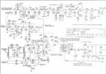
I'm a lot more familiar with the organ amps and not the tone cabinets, but if you look in the upper left corner of the schematic, it says Power Supply Chassis and just under the transformer it says eight wires to amp chassis, I do remember seeing only power chassis for sale. Now it makes sense. It appears that these were powered by a separate chassis connected with those six, seven and eight pin connectors. The best I can see is that the connectors provide the power and signal for this amp. I will do more research to shed more light on this as I'm learning a lot as I go along here too!
Last edited:
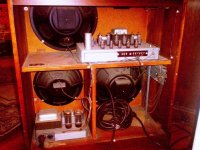
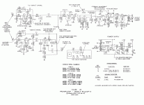
OK, that was faster than I thought. You see in the lower left is the power supply and in the upper part is your amp. So there is a connection between these and also to the organ. I guess it isn't connectors that connect these, just loose wires. Three channel amp, three speakers. 15-18 watts per channel. And if you look way to the right, on the bottom, those three springs hanging on the cab side, that is the original reverb "necklace" springs. These are the original reverb springs that started it all. These pre-date any reverb tank. In the bottom right, you can see the cord that goes to the organ. Click to enlarge.


Last edited:
Yes, the power supply that has a big tail that runs to the amp. So is there a way of directly powering the power supply without using the mains from the organ? Also how would I do an multiple input into the amp with out having a signal drop. My idea is to use a balanced xlr or 1/4 from the organ to the amp or other instrument and speakon out to the Leslie's
Sent from my iPhone using Tapatalk
Sent from my iPhone using Tapatalk
I think we're getting into territory I've not explored here. As I said before, I really am familiar with using the amps form the organs themselves, especially the L-100 series and M-100 reverb amps. This is just info I have come across while working on other amps. I'll keep digging but it will be totally new territory for me.
There's an organ tech that contributes to this forum, Indianajo I believe he goes by. Maybe you can PM him or he will see this.
There's an organ tech that contributes to this forum, Indianajo I believe he goes by. Maybe you can PM him or he will see this.
Ok, it would seem that you can take 120 mains and throw it on the 120 input voltage into the tone cabinet, I asked a electrician friend and he said that the power supply does in fact receive 115 from the organ and that adding a line directly to would be no issue as long as the polarities are correct and fused
Sent from my iPhone using Tapatalk
Sent from my iPhone using Tapatalk
And don't forget the 3rd ground wire in the 120v supply. That chassis needs a ground. Just get one of those crimp-on connectors and put it under a nearby nut. I did know this part, I just wasn't sure about the signal feed to the amp.
If you look in the middle of the top amp, it says "signal input from console" marked G1 and G2. This should be your input. It appears the signal is already split. That first tube V1, the 12AU7, is not a phase inverter tube. I believe the main console preamp has a transformer that splits the signal for the push pull type amp this is. So you will have to figure out how you are going to feed the amp with an already phase inverted signal.
The only other pin from the console to figure out is the one that says B+ 220v. It goes to the amp chassis but it is also in the connector from the organ so I don't know if it comes from the organ and is passed through or it is supplied form the power supply.
Last edited:
I recall that there's a wiring change in the amplifier (I presume in the power/output tube circuitry) to give the right-sounding "good distortion"/clipping at and near full output that was so often used in the 60-70s rock/pop Hammond sound. I don't know if it was the Hammond or the Leslie amp that was modified, but that might be something to look into. A quick look shows a lot of info online, but it's hard to know offhand what is correct.The nature of a Leslie is that distortion is not a critical issue and only reasonably flat frequency response is required.
On the other hand, if lighter weight equipment is (very) important, you can go with a chip amp for each driver (or maybe two in parallel for more power to the woofer), and use a line-level crossover. Perhaps a distortion circuit could be put in front of the crossover that adequately recreates the old modified tube amplifier's sound. But so far it seems all the talk has been about tube amps.
Didn't analyze the exact one you are modding now, but from past jobs I remember some old Hammond/Leslie combinations sent everything, including high current filament wiring and scary high voltages (think > 500V DC) from one to the other, through multi wire "umbilicals" , so if your tone cabinet demands one, you will have to build the proper power supply, there's no other way.
Your only flexibility might be either making it in an external chassis/cabinet and run the proper umbilical or build it inside .
You might also have to build a proper preamp, if needed.
Your only flexibility might be either making it in an external chassis/cabinet and run the proper umbilical or build it inside .
You might also have to build a proper preamp, if needed.
You need a preamp that has a phase inverter on the back end so you have the signal already split(inverted) and has about the same amount of gain. Here is the correct preamp for the C3. That transformer at the upper right does the PI function but you could use the standard tube PIs also. Those correspond to the G1 and G2 terminals we talked about earlier.But you still need to address that 220v pin 5 form the console to deal with. It is on the main amp schematic at the upper right. We talked about that earlier as well and I'm no sure what that's all about. Refer to post #27.


Last edited:
Yes, you can. But if you look at the upper left on the power supply chassis, where it says "from console" pin 5(center bottom) says 220v B+. Since it is on the connector from the console, it seems as though the console is supplying 220v DC B+voltage. It then is among the eight wires that you see at the bottom of the power supply that go from the power supply to the main amp. I don't know why they would do this since you have a power supply already. You could try just hooking up the 120v power and the two signal wires to see if it works. As I said, it doesn't make sense to send B+ power from the console if you already have a power supply to generate B+ power but the schematic says otherwise. And JM Fahey refers to this as well, although he thought 500v but was just stating what he recalled form a while ago.
You connect the 120v wall power to where pin 3 and 4 go and also need the grounded green wire to ground the chassis. Don't forget to add a switch and fuse as well. See what the power draw is form the nameplate on the power supply to figure out the fuse size.
Of course, this is all in reference to the schematic in post #16.
I wish I could help you more, but I an not a Hammond organ tech. This is just info I have come across working on other Hammond amps or just figured out for this post. At least you have a good start.
Last edited:
You'll need to keep in mind that the C3 has a balanced output and a Leslie 122 a balanced input. Motor control was a whole different issue with this model Leslie as they needed to find a way to achieve it over a 6-wire cable (which Leslie had thousands of feet available at the time and wanted to utilize). The answer was to impress a DC control voltage over one of the signal lines and remove it at the amplifier. If you're going to build a stock Leslie amp I'd look at a 147. It is single-ended and can be powered off either of the organ's 'G' terminal outputs. As for the crossover, follow the original schematic but by using newer components you'll avoid some of the more annoying distortion inherent with the Hammond/Leslie combination. The basic amplifier components, such as the transformers and power supply filter cap (a 3-stage 40uf @ 500v), are available from tonewheelgeneral.com or b3organ.com. Hammond and Leslie schematics are available at Hammond schematics here and elsewhere on the Net
Hope this helps. Bruce
Hope this helps. Bruce
- Status
- This old topic is closed. If you want to reopen this topic, contact a moderator using the "Report Post" button.
- Home
- Live Sound
- Instruments and Amps
- Need ideas for Leslie replace amp
