I'm a musician/composer/sound engineer type that sometimes delves into guitar electronics. I'm looking to further refine a circuit I have pieced together out of "found parts" online. I have managed to get a nice chunk of the circuit audibly working (and with enough volume), but there is, so far, too much noise in the signal, so I'm looking for quieter solutions. I also want to make sure the circuit is optimized (meaning, as safe and power efficient as possible) and to learn a few other control details like where to wire a high pass filter in the circuit.
The piezo sensors I have chosen are piezo film sensors (from Meas-Spec, basic DT Series). I've chosen piezo film over piezo buzzer elements due to piezo film's wide frequency range and lack of resonant frequency(s). I've wired three of these piezo film sensors in parallel and sandwiched them (spaced out such that each sensor is directly beneath two of the guitar strings) underneath the metal plate the bridge saddles sit on. For the sensors, I've used shielded cable and I've also grounded the bridge itself.
The link for the datasheet for the sensors is here:
DT Series?Piezo Sensors?Film Elements?Measurement Specialties
I want to make the circuit run off a single 9 volt. And I want to be able to install it inside my guitar, along with the magnetic pickup system. For now I am not going to bother trying to mix the two systems and I will simply have two output jacks, one for piezo, one for magnetic.
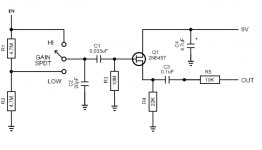
In order to buffer the piezo sensors I built a buffer circuit originally designed by Scott Helmke for bass but then adapted for guitar (see attachment 1):
http://www.diyguitarist.com/Guitars/PiezoBuffer.html
This makes the piezo sensors sound really quite good, but the level is much too low for my needs
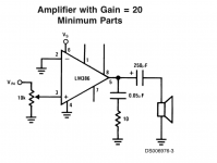
So I have simply added an LM386 opamp in "minimum parts" mode (see 2nd attachment) after the buffer. I have connected the two with the 10k resistor of the first buffer circuit being the 10 k pot at the beginning of the second opamp circuit. They share the same 9 volt source. Now I'm pretty pleased with the results except for the amount of noise in the signal. So in searching for a solution I came across this forum post:
[SOLVED] problem with audio amplifier using ne5532 / LM386 ic
In the discussion it is suggested to use a "NE5532 as a pre-amplifier to increase the overall gain", into the LM386 IC.
the datasheet for the NE5532 can be found here:
Operational Amplifier (Op Amp) - General Purpose Amplifier - NE5532 - TI.com
the NE5532 datasheet does not contain any "typical applications" schematics, so I am unsure how to proceed at the moment. I have seen circuits online that use the NE5532 with a 9 volt, so I believe that shouldn't be an issue.
Could anyone suggest a way to wire the NE5532 to the best effect? Any other relevant suggestions are greatly appreciated.
I have attached the schematics of the two circuits I have combined thus far
-Brett
The piezo sensors I have chosen are piezo film sensors (from Meas-Spec, basic DT Series). I've chosen piezo film over piezo buzzer elements due to piezo film's wide frequency range and lack of resonant frequency(s). I've wired three of these piezo film sensors in parallel and sandwiched them (spaced out such that each sensor is directly beneath two of the guitar strings) underneath the metal plate the bridge saddles sit on. For the sensors, I've used shielded cable and I've also grounded the bridge itself.
The link for the datasheet for the sensors is here:
DT Series?Piezo Sensors?Film Elements?Measurement Specialties
I want to make the circuit run off a single 9 volt. And I want to be able to install it inside my guitar, along with the magnetic pickup system. For now I am not going to bother trying to mix the two systems and I will simply have two output jacks, one for piezo, one for magnetic.
In order to buffer the piezo sensors I built a buffer circuit originally designed by Scott Helmke for bass but then adapted for guitar (see attachment 1):
http://www.diyguitarist.com/Guitars/PiezoBuffer.html
This makes the piezo sensors sound really quite good, but the level is much too low for my needs
So I have simply added an LM386 opamp in "minimum parts" mode (see 2nd attachment) after the buffer. I have connected the two with the 10k resistor of the first buffer circuit being the 10 k pot at the beginning of the second opamp circuit. They share the same 9 volt source. Now I'm pretty pleased with the results except for the amount of noise in the signal. So in searching for a solution I came across this forum post:
[SOLVED] problem with audio amplifier using ne5532 / LM386 ic
In the discussion it is suggested to use a "NE5532 as a pre-amplifier to increase the overall gain", into the LM386 IC.
the datasheet for the NE5532 can be found here:
Operational Amplifier (Op Amp) - General Purpose Amplifier - NE5532 - TI.com
the NE5532 datasheet does not contain any "typical applications" schematics, so I am unsure how to proceed at the moment. I have seen circuits online that use the NE5532 with a 9 volt, so I believe that shouldn't be an issue.
Could anyone suggest a way to wire the NE5532 to the best effect? Any other relevant suggestions are greatly appreciated.
I have attached the schematics of the two circuits I have combined thus far
-Brett
Attachments
hello.
for what reason did you choose the lm386? it is a small headphone amp.....;
with a 9v battery you can use low power consumtion opamps........;
if the input signal is low you can leave out the voltage divider (4,7meg) at the input......;
did you leave out the 10k pot at the input of the lm386?
and substitute it with a 10k res in series? ;
the cap's c1,c3 at the fet stage work as a "low pass filter" .
Last edited:
For years I have used a JFet as buffer in a die cast aluminium case feeding my stage box from acoustic guitar with no preamp for back-line feed to the FOH PA.
I use a FET, similar to your circuit with a differential output from a 5532 to send balanced line signal to my desk. I use either phantom power or the built in 9v battery.
I use a FET, similar to your circuit with a differential output from a 5532 to send balanced line signal to my desk. I use either phantom power or the built in 9v battery.
Thanks for the responses...
I chose the LM386 simply because there was a lot of information online about it... and for the simplicity of it... I'm definitely open to using different opamps... it's just that... in researching them... there didn't seem to be many that could run on a 9volt battery... but maybe I'm wrong there.
Could you suggest a good opamp for my application? (post "buffered" piezo signal). From the www.DIYguitarist.com Home Page site.... i just discovered.... as well as the piezo buffer circuit, there is a preamp circuit there using a NE5534... would that bring the noise level down, while still providing the gain I need?
I mean... if it were possible to buffer the signal at the same time as amplify it, well that would be great as well... but I don't have the electronics background to build circuits myself.... therefore, i resort to this combining of circuits I've found online, and testing through trial and error. I do have a multimeter but I'm still learning how to use it properly.
mjf, I actually have already bypassed the voltage divider and used the buffer circuit in permanent "high gain" setting... but it's still not enough volume. The piezo film elements I am using are not nearly as hot as hard piezo discs or under-the-saddle pickups... so I really need a lot of gain.... the LM386 provides more than enough gain... but it's too noisy
and... I actually did the opposite, I kept the 10k pot instead of the 10k resistor at the end of the buffer circuit... should I actually be keeping both the resistor and the pot?
- also thanks for the info on the caps that control the low frequencies/LPF effect... would I change either one... or both at the same time if I wanted to raise/lower the cutoff frequency? I'm bread boarding the circuit so, I can try different values for each
JonSnell, so you use a FET as well as a NE5532? Would it be possible, do you think, to use the same circuit but amplify the signal greatly, while still providing not too much noise? For my application, the piezo film sensors simply produce a much lower signal. I have them installed in my electric guitar under the bridge, so, the lack of body resonance also adds to the much lower volume output, when compared to an acoustic.
Last edited:
Thanks for the responses...
I chose the LM386 simply because there was a lot of information online about it... and for the simplicity of it... I'm definitely open to using different opamps... it's just that... in researching them... there didn't seem to be many that could run on a 9volt battery... but maybe I'm wrong there.
You are, on all counts - the LM386 isn't even an opamp, it's a small power amp. Most opamps will run off 9V without problem.
JonSnell, so you use a FET as well as a NE5532? Would it be possible, do you think, to use the same circuit but amplify the signal greatly, while still providing not too much noise? For my application, the piezo film sensors simply produce a much lower signal. I have them installed in my electric guitar under the bridge, so, the lack of body resonance also adds to the much lower volume output, when compared to an acoustic.
The FET is used to give a high input impedance, the opamp gives the gain - an OPA134 would be a decent choice as well, even quieter than the NE5532.
Thanks Nigel, I'm glad I was wrong in that case!
Just quickly checking out the OPA134 datasheet, I see it is designed specifically for audio as well... so I'll definitely research more there.
I noticed the OPA134 datasheet talks about a FET input stage included in the opamp, would I still need the original buffer circuit to precede the OPA134?
Just quickly checking out the OPA134 datasheet, I see it is designed specifically for audio as well... so I'll definitely research more there.
I noticed the OPA134 datasheet talks about a FET input stage included in the opamp, would I still need the original buffer circuit to precede the OPA134?
yes,you need a low noise opamp (like ne5532/5534,opa134/2134,opa604/2604,.....cheap tl071,lf351/353......etc.)
all of them should work with a 9v battery.
the caps that control the low frequency must be calculated after you have designed a schematic.......bigger caps let pass through lower frequencies vice versa small caps cut off deep tones.
all of them should work with a 9v battery.
the caps that control the low frequency must be calculated after you have designed a schematic.......bigger caps let pass through lower frequencies vice versa small caps cut off deep tones.
Last edited:
Thanks Nigel, I'm glad I was wrong in that case!
Just quickly checking out the OPA134 datasheet, I see it is designed specifically for audio as well... so I'll definitely research more there.
I noticed the OPA134 datasheet talks about a FET input stage included in the opamp, would I still need the original buffer circuit to precede the OPA134?
Try it and see - but adding an FET front end allows you to more easily plug different opamps in to try, as you can then use almost any opamp and see which you prefer.
ok great! Thanks again for the info Nigel and mjf.
I have purchased an OPA2134 (I asked for OPA134... but found out when I got home it was the 2134 instead.... I don't think it makes an audible difference except for a couple pin changes, please correct me if I'm wrong) and an OPA604 and will test them both in a breadboard setup.
I'll post the results.
Does anyone know.... will 1/4 watt resistors be enough for the entire circuit... or should I upgrade the ones after the opamp?
The OPA2134 is a dual op amp, the OPA134 is a single. You will find that the OPA2134 is much more common. There is also a OPA4134 with 4 opamps in a 14 pin package.
Since the OPA2134 op amp is a J FET input then there should be no need to use an external J FET buffer ahead of it to achieve the required high impedance input to suit the Piezo Sensor.
One thing bothers me about the Piezo Buffer design shown. The reason that a high impedance input to the buffer is required is that the Piezo is highly capacitive. Without the high impedance buffer input you loose bass. I think that the additional capacitor to 0V shown on the buffer schematic (at teh input) is only going to reduce the input signal by capacitor divider action without giving any worthwhile frequency shaping. This will just result in a noisier system.
Cheers,
Ian
One thing bothers me about the Piezo Buffer design shown. The reason that a high impedance input to the buffer is required is that the Piezo is highly capacitive. Without the high impedance buffer input you loose bass. I think that the additional capacitor to 0V shown on the buffer schematic (at teh input) is only going to reduce the input signal by capacitor divider action without giving any worthwhile frequency shaping. This will just result in a noisier system.
I presumed the capacitor was to help prevent RFI?, not for any tone shaping properties.
However, I don't like the high/low attenuator at the front which halves the input impedance - if you need a high/low switch then stick another 10meg in series with the input, and put a switch across it (giving 10meg or 20meg input impedance).
I presumed the capacitor was to help prevent RFI?, not for any tone shaping properties.
Bad manners to reply to your own thread
 , but I've just done the calculations on the 20pF - it's certainly a BAD idea to fit it, as it's reactance is 10meg at only 800Hz or so, so it will have a fairly major effect on loading of the PU.
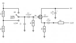
Ah I should carify. After he posted the circuit, he suggested to use 1pF instead of 20pF... to "shunt" the RF.
I've tried the circuit quickly, but haven't found enough gain for my application. I'll go over the circuit and try some things... I'll also try the opamp circuit alone, as Gingertube has suggested.
I've tried the circuit quickly, but haven't found enough gain for my application. I'll go over the circuit and try some things... I'll also try the opamp circuit alone, as Gingertube has suggested.
So... I have tried the opamp circuit posted with the OPA2134... alone... without the FET buffer circuit, and it sounds pretty good. I've changed the resistor in the feedback loop to increase the gain... from 100K up to 1.2M... now I'm happy with the gain... but the high frequencies have been cut now... a kind of LPF effect... not terrible... but... I wanted to use piezos (over magnetic pickups) to INCREASE the high frequency content... not cut it.
Any ideas?
Any ideas?
So... I have tried the opamp circuit posted with the OPA2134... alone... without the FET buffer circuit, and it sounds pretty good. I've changed the resistor in the feedback loop to increase the gain... from 100K up to 1.2M... now I'm happy with the gain... but the high frequencies have been cut now... a kind of LPF effect... not terrible... but... I wanted to use piezos (over magnetic pickups) to INCREASE the high frequency content... not cut it.
Where is the circuit?.
If you've increased the gain too much, then you lose high frequencies - it's a basic limitation of opamps, and given in the specifications. The solution is to use more stages, with lower gain in each stage.
I've just temporarily bypassed the FET buffer circuit on a breadboard... I still have it... in fact that's the next thing I'll try... adding the two circuits together again... to see how that affects the gain stages. Maybe a better solution would be to use the OPA604 as well? What about if I use ONLY the OPA2134 but use BOTH amps within it? Is this possible?
One other potentially important question I had... is it possible to use a single 9 volt for 2 simultaneous circuits such as this? Or is it better to have one 9 volt for each circuit?
One other potentially important question I had... is it possible to use a single 9 volt for 2 simultaneous circuits such as this? Or is it better to have one 9 volt for each circuit?
I've just temporarily bypassed the FET buffer circuit on a breadboard... I still have it... in fact that's the next thing I'll try... adding the two circuits together again... to see how that affects the gain stages. Maybe a better solution would be to use the OPA604 as well? What about if I use ONLY the OPA2134 but use BOTH amps within it? Is this possible?
That's why it has two amps inside
One other potentially important question I had... is it possible to use a single 9 volt for 2 simultaneous circuits such as this? Or is it better to have one 9 volt for each circuit?
Easily possible, and preferable - if you're going to use 2x9V batteries, then use them as a +/-9V split supply.
You are, on all counts - the LM386 isn't even an opamp, it's a small power amp. Most opamps will run off 9V without problem.
The FET is used to give a high input impedance, the opamp gives the gain - an OPA134 would be a decent choice as well, even quieter than the NE5532.
As the impedance of the FET is above 4M7 then the signal from the buffered FET is around 700mV so not a lot of gain is required. Leave the gain requirements to your mixer!
As the impedance of the FET is above 4M7 then the signal from the buffered FET is around 700mV so not a lot of gain is required. Leave the gain requirements to your mixer!
According to the OP he's had to INCREASE the gain of the opamp in order to make it work, it obviously really depends on the output level from his source. If the source is high level, then a simple FET buffer would be all that's needed.
- Status
- This old topic is closed. If you want to reopen this topic, contact a moderator using the "Report Post" button.
- Home
- Live Sound
- Instruments and Amps
- Piezo Film Buffer and Amp Combo for Guitar Electronics