Yes Nigel is right, the level of the piezo film is very low... it is possible to get piezo film that outputs a higher level, but right now it costs 20x the money... because it's non standard. I've already tried the buffer circuit alone extensively, it sounds great (balanced frequency spectrum), but in order to hear it I have to max my computer's external audio card, and the amount of noise is unacceptable.
Nigel, do you know... if I ran the signal through both sides of the OPA2134... would any of the circuit component values change the second time around (i.e. after the first opamp in the 2134)?
Nigel, do you know... if I ran the signal through both sides of the OPA2134... would any of the circuit component values change the second time around (i.e. after the first opamp in the 2134)?
Yes Nigel is right, the level of the piezo film is very low... it is possible to get piezo film that outputs a higher level, but right now it costs 20x the money... because it's non standard. I've already tried the buffer circuit alone extensively, it sounds great (balanced frequency spectrum), but in order to hear it I have to max my computer's external audio card, and the amount of noise is unacceptable.
Nigel, do you know... if I ran the signal through both sides of the OPA2134... would any of the circuit component values change the second time around (i.e. after the first opamp in the 2134)?
You don't need a high impedance input on the second amp, as it's fed from a low impedance source (the first opamp).
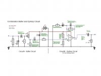
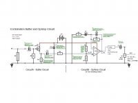
Hey there, I've finally found some time to dig into this circuit, my updated circuit is in the PDF attachment. I've added annotations (small green text) regarding what I've found in my research, if you want to read them you have to zoom in.
So far, I've found that using the buffer circuit really helps in balancing the lows, so I've ruled out using the opAmp circuit alone.
Any notes regarding potential optimizations of this circuit are appreciated.
Specifically, I am looking for information regarding the main tone shaping components in the circuit. Would it be fair to call C1, C3, C5, and C8 all "audio coupling capacitors? Also, would I be right to call this an AC circuit, or is it also necessary to think about it in terms of DC?
Thanks for the responses thus far,
- Brett
Attachments
Specifically, I am looking for information regarding the main tone shaping components in the circuit. Would it be fair to call C1, C3, C5, and C8 all "audio coupling capacitors?
Yes, all are coupling capacitors - although there seems no point in having both C3 and C5 (or R5 at all).
You don't use coupling capacitors for tone shaping, their action is far too gentle.
Thanks for the info Nigel. I found online the equation C(new) = (C1*C2)/(C1+C2)... and calculated the result to be .018uF.... so... then... I would just leave the .022uF capacitor and get rid of C3 and R5?
I haven't figured out measuring impedance yet... but I'm thinking that might be the next step.
I haven't figured out measuring impedance yet... but I'm thinking that might be the next step.
Thanks for the info Nigel. I found online the equation C(new) = (C1*C2)/(C1+C2)... and calculated the result to be .018uF.... so... then... I would just leave the .022uF capacitor and get rid of C3 and R5?
Assuming you're wanting a 3dB/Oct bass roll off then 0.022 should be fine, but it's not really very much of a roll off.
I haven't figured out measuring impedance yet... but I'm thinking that might be the next step.
Measuring the impedance of what?.
hello.
R5 can be seen as a damping res against hf.......
It's not a valve amplifier

Assuming you're wanting a 3dB/Oct bass roll off then 0.022 should be fine, but it's not really very much of a roll off.
So would a higher value cap create a steeper roll off? For example, a 1uF cap might provide a 6dB/Oct bass roll off? I thought a cap here would more affect the cutoff frequency... or does it control BOTH cutoff frequency AND roll off "Q"/slope? Ideally, I'd like a fairly steep roll off at about 60Hz.
Measuring the impedance of what?.
I was thinking it would be enlightening to measure impedance at the output of the first circuit and the input of the second circuit. I was thinking this would help with knowing the right value capacitor to place there... for the most transparent audio signal.
Last edited:
you should swap the position of c8 /r10 (or you will have some dc current through the pot).......
if you do not really need the pot (r10) you can leave it out.......
well I need the pot (at least SOMEWHERE in the circuit)... as this is how I am adjusting the volume after the circuit is installed in my guitar....
so simply swap C8 with R10? mjf, I noticed you swapped the polarity of C8 as well... was the original drawing of the circuit (that I got online) wrong? I've tested the original circuit out already and the cap hasn't exploded... doesn't this prove then that some directional caps be used unidirectionally?
volume control:
a) you can substitute R11 with pot R10 at the output.
or b) build in a pot in position of R8 ,this gives you a gain control.
here we have only around 4,5V at the electrolytic cap. if the cap is rated way above this, the cap will quit slowly to deserve. with exceeding voltage above the rating it can explode........
Last edited:
So would a higher value cap create a steeper roll off? For example, a 1uF cap might provide a 6dB/Oct bass roll off? I thought a cap here would more affect the cutoff frequency... or does it control BOTH cutoff frequency AND roll off "Q"/slope? Ideally, I'd like a fairly steep roll off at about 60Hz.
It only affects the 'cut off' frequency - although it's so slight 'cut off' isn't really the correct word
You don't use coupling capacitor for filtering, they have far too little effect.
If you want filtering, add filters.
I was thinking it would be enlightening to measure impedance at the output of the first circuit and the input of the second circuit. I was thinking this would help with knowing the right value capacitor to place there... for the most transparent audio signal.
The input of the second is simple and obvious, the two 470K resistors in parallel.
The output impedance of the FET buffer is low enough to be ignored.
Sorry for being very late to this conversation, but if you still want circuits on the NE5532, here is a nice little appliction note on using them
http://rf-highvoltage.comxa.com/spec-sheets/NE5532-Audio-Circuits.pdf
http://rf-highvoltage.comxa.com/spec-sheets/NE5532-Audio-Circuits.pdf
volume control:
a) you can substitute R11 with pot R10 at the output.
or b) build in a pot in position of R8 ,this gives you a gain control.
well I definitely want a full volume control (down to silence) rather than a gain control....so, I would choose the first mod you suggested
Just to clarify: I would get rid of R11 (100k), and put R10 in its place (1k).... or should I make the new pot 100k?... also... I would put the pot directly in the audio path wouldn't I... rather than just on that branch down to ground?
here we have only around 4,5V at the electrolytic cap. if the cap is rated way above this, the cap will quit slowly to deserve. with exceeding voltage above the rating it can explode........
so I gather (from your earlier post) that the idea is to use the cap, in the direction you described in your drawing, to block DC... but will it eventually fail and need to be replaced? Or will it fail so slowly as to be nonsignificant? right now for these coupling capacitors I'm using "orange drops"... rated at 600v
well I definitely want a full volume control (down to silence) rather than a gain control....so, I would choose the first mod you suggested
Just to clarify: I would get rid of R11 (100k), and put R10 in its place (1k).... or should I make the new pot 100k?... also... I would put the pot directly in the audio path wouldn't I... rather than just on that branch down to ground?
Simply replace R11 with a pot (I would suggest 5K or 10K), and take the output off it's slider (as R10 is wired). Remove R10, and connect the capacitor directly from opamp to the new pot.
so I gather (from your earlier post) that the idea is to use the cap, in the direction you described in your drawing, to block DC... but will it eventually fail and need to be replaced? Or will it fail so slowly as to be nonsignificant? right now for these coupling capacitors I'm using "orange drops"... rated at 600v
Caps don't 'slowly fail' (apart from normal lifetime expectancy), there's no problem using higher voltage capacitors than you need. 'Generally' small electrolytic's (1uF, 2.2uF etc. are small enough even at 100V, so it makes no sense to stock lower voltage ones).
Non-electrolytics have no problems either.
good morning.
R12 is an optional part, a protection res.........(against short at the output).
I've no problem with R12 (although I doubt it's needed), but what's the reasoning for R5? - it does absolutely nothing.
Thanks TorontoBob for the info, but I'm pretty set on using an OPA2134 for this application, though I'll have a look through the PDF and see if any of the info can generalize to this circuit.
Thanks again mjf and Nigel for helping with the details of the circuit. Do you guys go through each circuit and actually calculate specific values... or do you simply know through experience what works and what doesn't?
Thanks again mjf and Nigel for helping with the details of the circuit. Do you guys go through each circuit and actually calculate specific values... or do you simply know through experience what works and what doesn't?
The input of the second is simple and obvious, the two 470K resistors in parallel.
so would the input impedance of the opAmp circuit be 235Kohms?
is the output impedance of the entire circuit so easily calculated?
so would the input impedance of the opAmp circuit be 235Kohms?
Yes, opamps make life VERY, VERY simple.
is the output impedance of the entire circuit so easily calculated?
'Sort of' - it's LOW
Basically it's low enough not to need to worry about, and it mostly can be ignored. If output impedance is a concern, then you should be looking at a power amp, not an opamp.
Designing with opamps is easy, because their purpose in life is to let you assume a number of things:
1) Gain - infinite.
2) Input impedance - infinite.
3) Output impedance - zero.
None of those is actually true, but they are near enough to be assumed so in the calculations.
- Status
- This old topic is closed. If you want to reopen this topic, contact a moderator using the "Report Post" button.
- Home
- Live Sound
- Instruments and Amps
- Piezo Film Buffer and Amp Combo for Guitar Electronics