
thinking about doing something in like this, instead of my Aikido board
one channel in, two channel out, with only one tube
any reason not to ?
ofcourse now I definately will need the BA-3 solid state output/gain stage
or maybe throw it all away, get over it, and just feed my pedals directly into active xo
one channel in, two channel out, with only one tube
any reason not to ?
ofcourse now I definately will need the BA-3 solid state output/gain stage
or maybe throw it all away, get over it, and just feed my pedals directly into active xo
Attachments

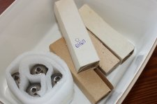
man, why do I buy all this stuff 
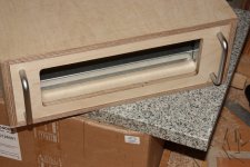
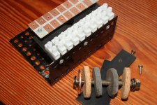
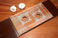
but now that I have a couple of these LDR att boards, and some matched LDR as well, why not try and put it in there
well, all effects have their own attenuator, so it I guess it will have its natural place at tube pre out
and this way be able to control both channels of my stereo power amp
now is that not clever or what
you are invited to argue on that
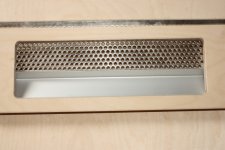
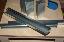
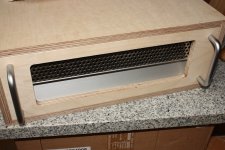
btw
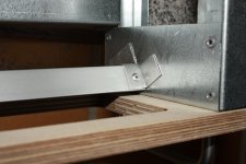
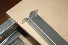
I just managed to construct a backplate from my leftover (s)crap profiles
oh, and them nice mounting screw are from a scrapped PC
but now that I have a couple of these LDR att boards, and some matched LDR as well, why not try and put it in there
well, all effects have their own attenuator, so it I guess it will have its natural place at tube pre out
and this way be able to control both channels of my stereo power amp
now is that not clever or what
you are invited to argue on that
btw
I just managed to construct a backplate from my leftover (s)crap profiles
oh, and them nice mounting screw are from a scrapped PC
Attachments
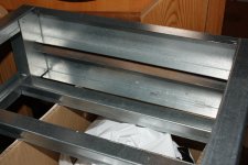
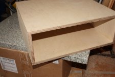
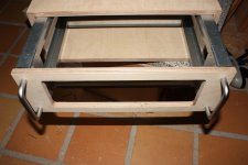
time to get on with it
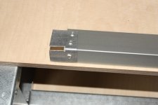
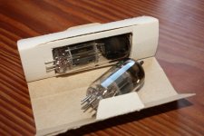
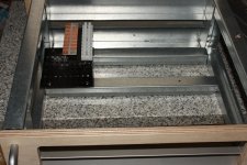
hmm, 90mm clearence should just about do it for the bigger 6n6p
man, I still havent got around to the lacquer
front need to be assembled for that
sets me back some
its definately next on the list
and ordering hardware bits and pieces
hmm, 90mm clearence should just about do it for the bigger 6n6p
man, I still havent got around to the lacquer
front need to be assembled for that
sets me back some
its definately next on the list
and ordering hardware bits and pieces
Attachments
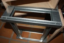
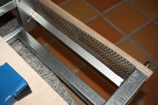
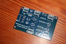
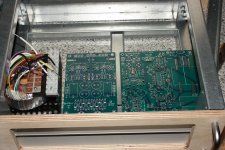
seems like I have to make a few small changes to the chassis, and rearrange a bit, not to waste too much space
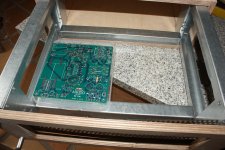
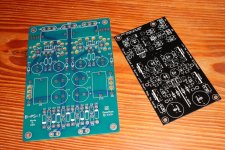
but man, Broskie's boards are just so bloody big
not to be hard on him, but only shows how high the level is here, among our own members
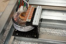
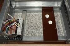
green one is a regulated supply from Broskie
just plain basic design, and still so fu... big
would never have bought it, had I known this
and the neat black one is 'our own' Hynotize symmetric B1 jfet buffer with shunt regulation, twice as much, and less than half size
well, admittedly, even the pros might find it hard to compete with this
but man, Broskie's boards are just so bloody big
not to be hard on him, but only shows how high the level is here, among our own members
green one is a regulated supply from Broskie
just plain basic design, and still so fu... big
would never have bought it, had I known this
and the neat black one is 'our own' Hynotize symmetric B1 jfet buffer with shunt regulation, twice as much, and less than half size
well, admittedly, even the pros might find it hard to compete with this
Attachments
call me nuts
but now seriously thinking about cutting the copper traces to the tube sockets, and hardwire the 6n1p and 6n6p for a double mu stage follower
I think it should work ok with half 6n6p for top triode, and half 6n1p for bottom triode
that would give two channels, or stereo out, if you like
might be more convenient to have a stereo preamp, later on
funny that there is actually a 2-channel out, with plenty of space for two big output caps, on this mono board
maybe I will cut it away, maybe I wont, dont know yet
but the space is actually one third of the board
but if I it cut away, it may still be of use to hold the caps, and placed somewhere else more convenient
maybe I will be able to use some of the copper traces

man it pains, but might have to be
but now seriously thinking about cutting the copper traces to the tube sockets, and hardwire the 6n1p and 6n6p for a double mu stage follower
I think it should work ok with half 6n6p for top triode, and half 6n1p for bottom triode
that would give two channels, or stereo out, if you like
might be more convenient to have a stereo preamp, later on
funny that there is actually a 2-channel out, with plenty of space for two big output caps, on this mono board
maybe I will cut it away, maybe I wont, dont know yet
but the space is actually one third of the board
but if I it cut away, it may still be of use to hold the caps, and placed somewhere else more convenient
maybe I will be able to use some of the copper traces
man it pains, but might have to be
...... 6n1p and 6n6p for a double mu stage follower
but a simple gain stage with cathode follower might make more sense
a possible attenuator pot would then be buffered
and the preamp would work work 'as is'
call me nuts
but now seriously thinking about cutting the copper traces ...
maybe I will cut it away....
man it pains, but might have to be
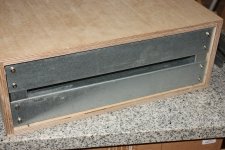
no, I could not do it
sure hope I'm still in the clear with the Aikido guys
but I can use the parts, and not loosing any sleep
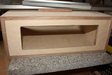
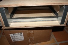
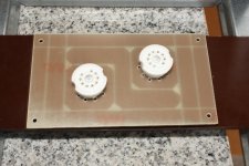
so I'm doing this instead
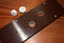
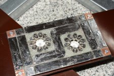
well, the copper print will be underneath the brown plate
just need a couple of big holes for the sockets
Attachments
well, the copper print will be underneath the brown plate
just need a couple of big holes for the sockets
like this
Attachments
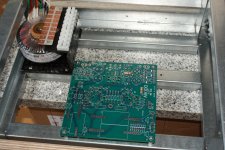
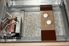
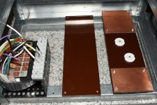
hey, got the idea; why not place a couple more prints, and prepare for the optional solid state output, or whatever
and got the copper side tinned
and another brown plate to hold the various power supply curcuits needed
might look neat with some axial supply caps
and got the copper side tinned
and another brown plate to hold the various power supply curcuits needed
might look neat with some axial supply caps
Attachments
- Status
- This old topic is closed. If you want to reopen this topic, contact a moderator using the "Report Post" button.
- Home
- Live Sound
- Instruments and Amps
- Switchable Hi-Z input impedance, how ?