An externally hosted image should be here but it was not working when we last tested it.
http://www.webphix.com/schematic heaven/www.schematicheaven.com/fenderamps/tremolux_6g9a_h-fa.pdf
Full schematic link is above.
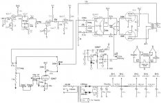
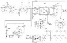
This is the oscillator section of the Fender 6g9a Tremolux. What is the function of that 0.05u cap on the top right? Is it merely filtering noise or is all/some of the trem signal flowing thru it to ground? Does it perform any non-trem related functions given the fact it's connected to the junction of the output's grid leaks? What would be the result(s) of increasing or decreasing it's value?
In my application it has cathode biased outputs and the other outer lug on the intensity pot is grounded.
It filters out harmonics of modulating signal, so it is more sinewave. If you increase it's value you get less deep tremolo, but more silewave control. And vice verse.
Edit: if right end of your pot is grounded it does not make it "more sinewave" when turns down, instead it turns down tremolo down to zero.
Edit: if right end of your pot is grounded it does not make it "more sinewave" when turns down, instead it turns down tremolo down to zero.
Last edited:
if right end of your pot is grounded it does not make it "more sinewave" when turns down, instead it turns down tremolo down to zero.
The right end of the pot is at AC ground, so the pot is a "volume" pot on the tremelo signal. This circuit is one of the old Fender designs where they used the minimum amount of components needed to do the job.
The right end of the intensity pot is connected to the negative bias supply, the wiper goes to the 6L6GC grid resistors. The .05 uF cap is the typical bypass for the bias circuit and provides a low impedance at audio frequencies. All is well when all of the parts are good. When the pot goes bad the output tubes blow up. When the caps get leaky the intensity control sets the intensity of the glow in the output tubes. I have seen one where the plate glow pulsated with the tremelo.
In your circuit the value of the cap should not make much difference unless it is big enough to attenuate the tremelo frequency.
I have to agree with Wavebourn here. The output of the tremolo oscillator will have a pointy transition when the tube turns on and off. this can sound like a ticking noise in the background. The .05 tends to attenuate the transition noise. I have seen amps with weak filter caps also exibit this noise. A larger cap here will make for a more sinusoidal waveform, but at the cost of tremolo depth at the higher oscillator rates.
In my case the right (top) side of the pot is grounded. This because there is no grid bias since mine is cathode biased. I'm seeing some other (cathode biased) models that use the same basic trem approach that don't have that cap. In my case the trem does not push the tubes into cutoff, at least when idling. Almost but not quite. Of course they reach cutoff sooner with signal but not into crossover distortion.
My trem has not been as sine wave shaped as I would prefer but I was wondering about the value of the cap since some don't have it and some use 0.1u. I'm using 0.05u. I didn't know if these ranges would affect the impedance at typical guitar frequencies since the cap bypasses the trem pot which is in the grid leak circuit. Maybe I'll try a 0.1u and see what happens.
My trem has not been as sine wave shaped as I would prefer but I was wondering about the value of the cap since some don't have it and some use 0.1u. I'm using 0.05u. I didn't know if these ranges would affect the impedance at typical guitar frequencies since the cap bypasses the trem pot which is in the grid leak circuit. Maybe I'll try a 0.1u and see what happens.
Attachments
I tried 0.1u and the wave is smoother but the effect a little weaker. I did a lot of work to get this trem to be strong enough at all volume settings. I'm thinking of using a higher value pot. I think I have room there based on some circuits I’ve seen.
For example, my friend used his Ampeg Mercury at a gig the other day where I was running sound. His trem was fantastic sounding. I didn't have my scope yet when I working on his amp a few years ago, so I haven't seen it's wave. Looking at his scheme (attached) I see that his trem doesn't have "that cap" and it's coming off a plate. However, it comes off a triode that being modulated at it's cathode. Just like the "bottom" half of a LTPI. I guess this could make the wave smoother?
Any other ideas on getting a more sine like wave that's still strong?
Attachments
I decided to try a 12aT7 to see what would happen. The wave looked almost perfect but was significantly weaker. And it would not oscillate at lower speeds. And the led indicator in the cathode didn’t fully blink. So I went thru about 10 in my 12aX7 stash and happened to find two that happened to idle hotter on the oscillating side (and thus colder on the DC-coupled cathode follower.) These two tubes also happened to show more sinusoidal waves than the “normal” idling units. I had used cooler biasing before so I think it’s about the tube’s characteristic than the bias setting. Each put out only about 2-3volts less trem signal than the others. One was clipping on the bottom a little so I went with the other one. It’s a long black plated Sylvania. I increased the overall output strength by eliminating a resistor in line to the intensity control pot. It’s definitely better now.
Before starting the tube switching I wanted to see how the cathode follower side was idling and check the load line. I have the Valve Wizard’s excel file but how do you do enter a DC coupled cathode follower?
Before starting the tube switching I wanted to see how the cathode follower side was idling and check the load line. I have the Valve Wizard’s excel file but how do you do enter a DC coupled cathode follower?
Attachments
- Status
- This old topic is closed. If you want to reopen this topic, contact a moderator using the "Report Post" button.
- Home
- Live Sound
- Instruments and Amps
- That mystery trem cap